Universal synchronous/asynchronous receiver transmitter (USART/UART) RM0440
1610/2126 RM0440 Rev 4
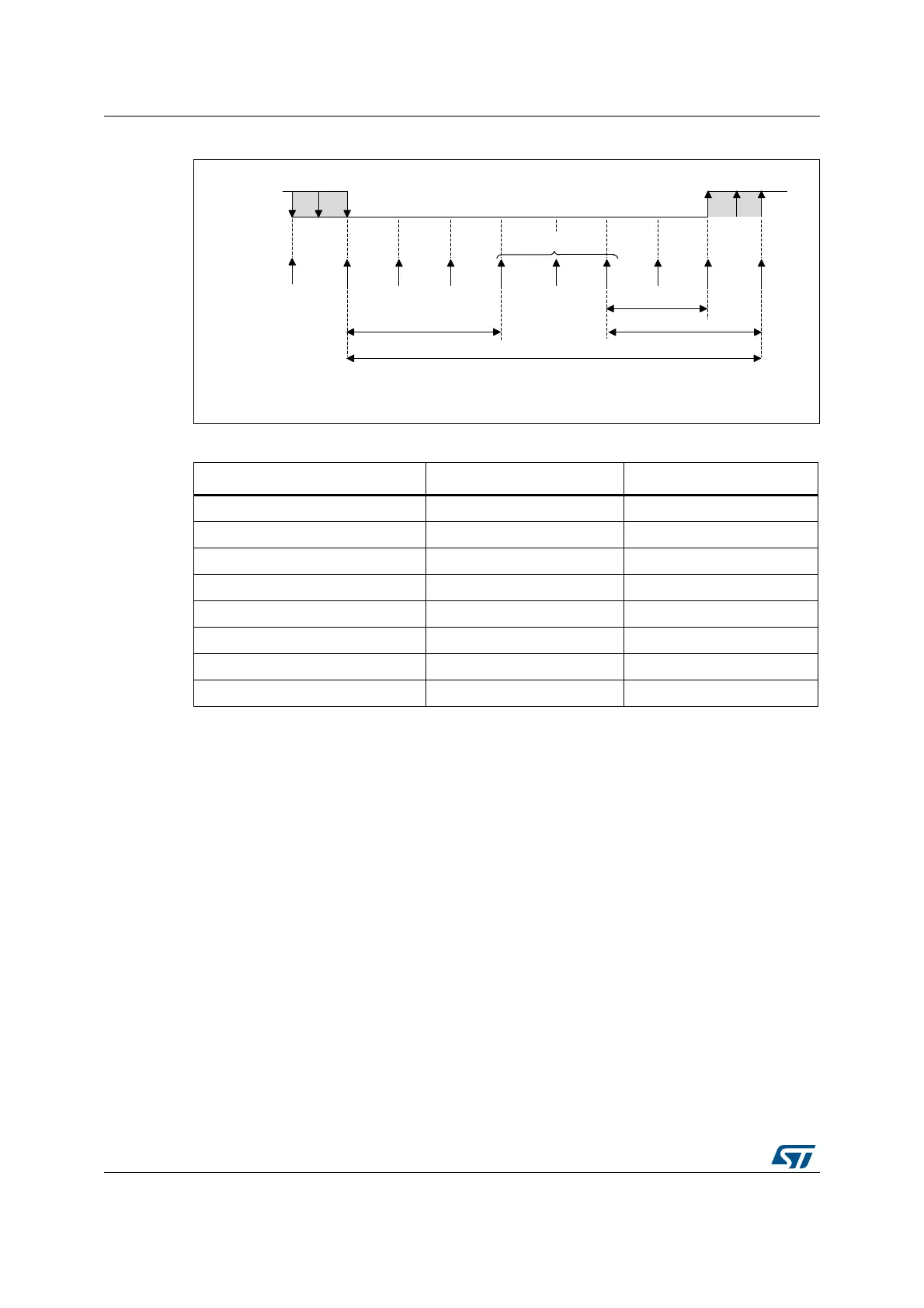
Figure 537. Data sampling when oversampling by 8
Framing error
A framing error is detected when the stop bit is not recognized on reception at the expected
time, following either a de-synchronization or excessive noise.
When the framing error is detected:
• the FE bit is set by hardware;
• the invalid data is transferred from the Shift register to the USART_RDR register
(RXFIFO in case FIFO mode is enabled).
• no interrupt is generated in case of single byte communication. However this bit rises at
the same time as the RXNE bit (RXFNE in case FIFO mode is enabled) which itself
generates an interrupt. In case of multibuffer communication an interrupt is issued if the
EIE bit is set in the USART_CR3 register.
The FE bit is reset by writing ‘1’ to the FECF in the USART_ICR register.
Note: Framing error is not supported in SPI mode.
Table 344. Noise detection from sampled data
Sampled value NE status Received bit value
000 0 0
001 1 0
010 1 0
011 1 1
100 1 0
101 1 1
110 1 1
111 0 1
MSv31153V1
1 2 3 4 5 6 7
sampled values
2/8
3/8
3/8
One bit time
Sample
clock (x8)
RX line
8
 Loading...


