FD controller area network (FDCAN) RM0440
1944/2126 RM0440 Rev 4
44 FD controller area network (FDCAN)
44.1 Introduction
The controller area network (CAN) subsystem (see Figure 662) consists of one CAN
module, a shared message RAM and a configuration bloc. Refer to the memory map for the
base address of each of these parts.
The modules (FDCAN) are compliant with ISO 11898-1: 2015 (CAN protocol specification
version 2.0 part A, B) and CAN FD protocol specification version 1.0.
A 0.8-Kbyte message RAM per FDCAN instance implements filters, receive FIFOs, transmit
event FIFOs and transmit FIFOs.
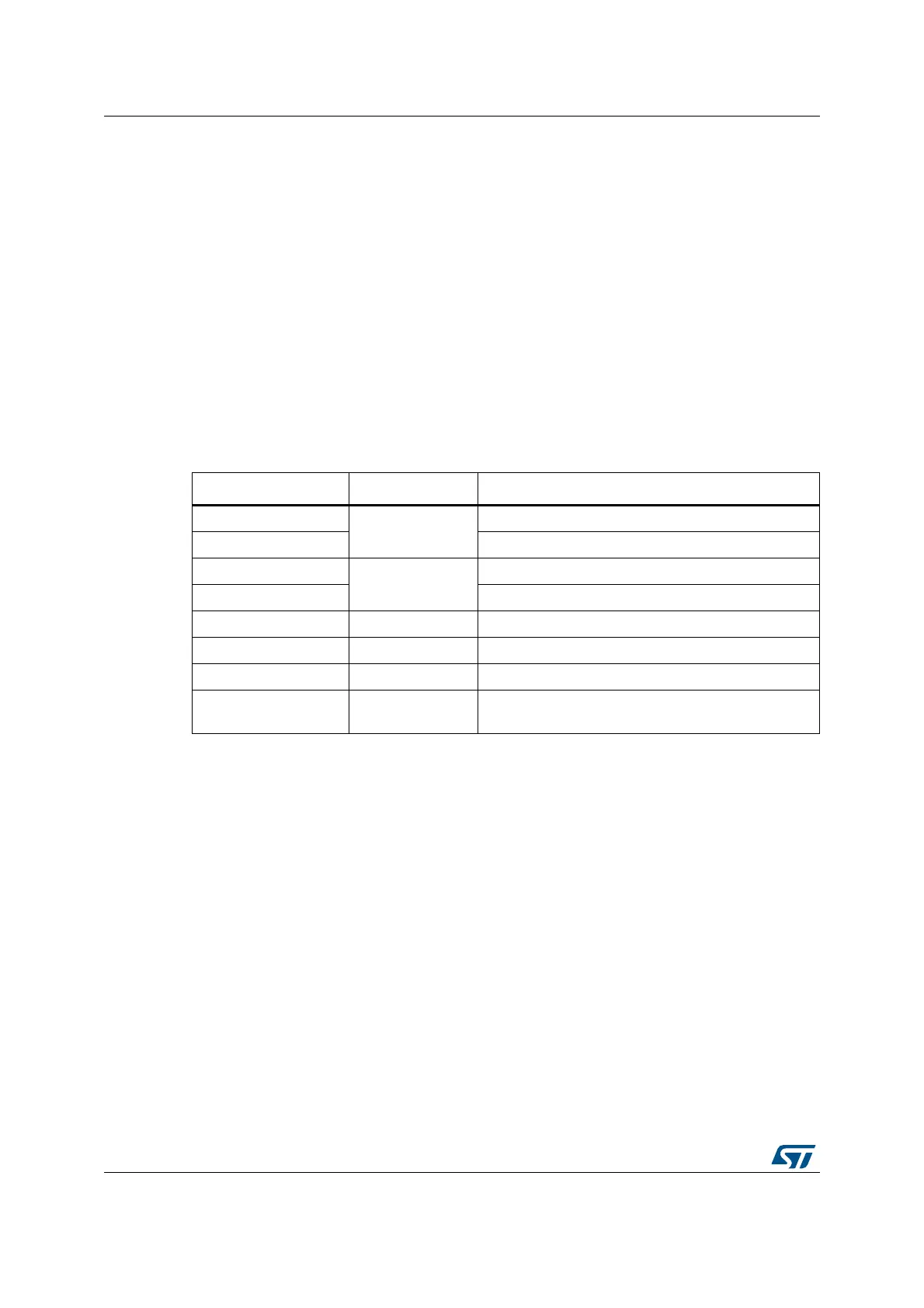
The CAN subsystem I/O signals and pins are detailed, respectively, in Table 393 and
Figure 662.
Table 393. CAN subsystem I/O signals
Name Type Description
fdcan_ck
Digital input
CAN subsystem kernel clock input
fdcan_pclk CAN subsystem APB interface clock input
fdan_intr0_it
Digital output
FDCAN interrupt0
fdan_intr1_it FDCAN interrupt1
fdcan_ts[0:15] - External timestamp vector
FDCAN_RX Digital input FDCAN receive pin
FDCAN_TX Digital output FDCAN transmit pin
APB interface Digital input/output
Single APP with multiple psel for configuration, control
and RAM access
 Loading...


