RM0440 Rev 4 1609/2126
RM0440 Universal synchronous/asynchronous receiver transmitter (USART/UART)
1733
usart_ker_ck_pres/16 (where usart_ker_ck_pres is the USART input clock divided by a
prescaler).
Programming the ONEBIT bit in the USART_CR3 register selects the method used to
evaluate the logic level. Two options are available:
• The majority vote of the three samples in the center of the received bit. In this case,
when the 3 samples used for the majority vote are not equal, the NE bit is set.
• A single sample in the center of the received bit
Depending on your application:
– select the three sample majority vote method (ONEBIT=0) when operating in a
noisy environment and reject the data when a noise is detected (refer to
Figure 344) because this indicates that a glitch occurred during the sampling.
– select the single sample method (ONEBIT=1) when the line is noise-free to
increase the receiver tolerance to clock deviations (see Section 37.5.8: Tolerance
of the USART receiver to clock deviation on page 1612). In this case the NE bit is
never set.
When noise is detected in a frame:
• The NE bit is set at the rising edge of the RXNE bit (RXFNE in case of FIFO mode
enabled).
• The invalid data is transferred from the Shift register to the USART_RDR register.
• No interrupt is generated in case of single byte communication. However this bit rises
at the same time as the RXNE bit (RXFNE in case of FIFO mode enabled) which itself
generates an interrupt. In case of multibuffer communication an interrupt is issued if the
EIE bit is set in the USART_CR3 register.
The NE bit is reset by setting NECF bit in USART_ICR register.
Note: Noise error is not supported in SPI mode.
Oversampling by 8 is not available in the Smartcard, IrDA and LIN modes. In those modes,
the OVER8 bit is forced to ‘0 ’ by hardware.
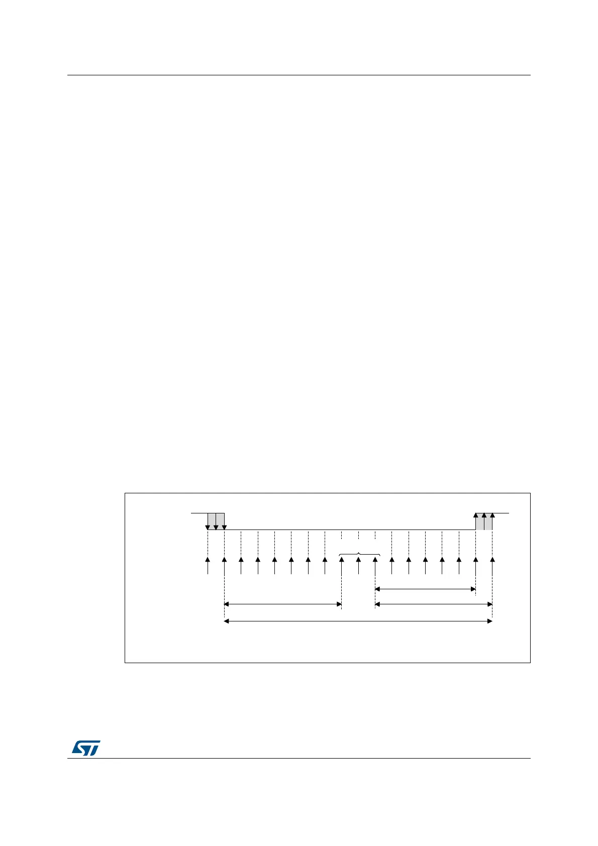
Figure 536. Data sampling when oversampling by 16
MSv31152V1
1 2 3 4 5 6 7 8 9 10 11 12 13 14 15 16
sampled values
6/16
7/167/16
One bit time
Sample clock
RX line
 Loading...


