High-resolution timer (HRTIM) RM0440
926/2126 RM0440 Rev 4
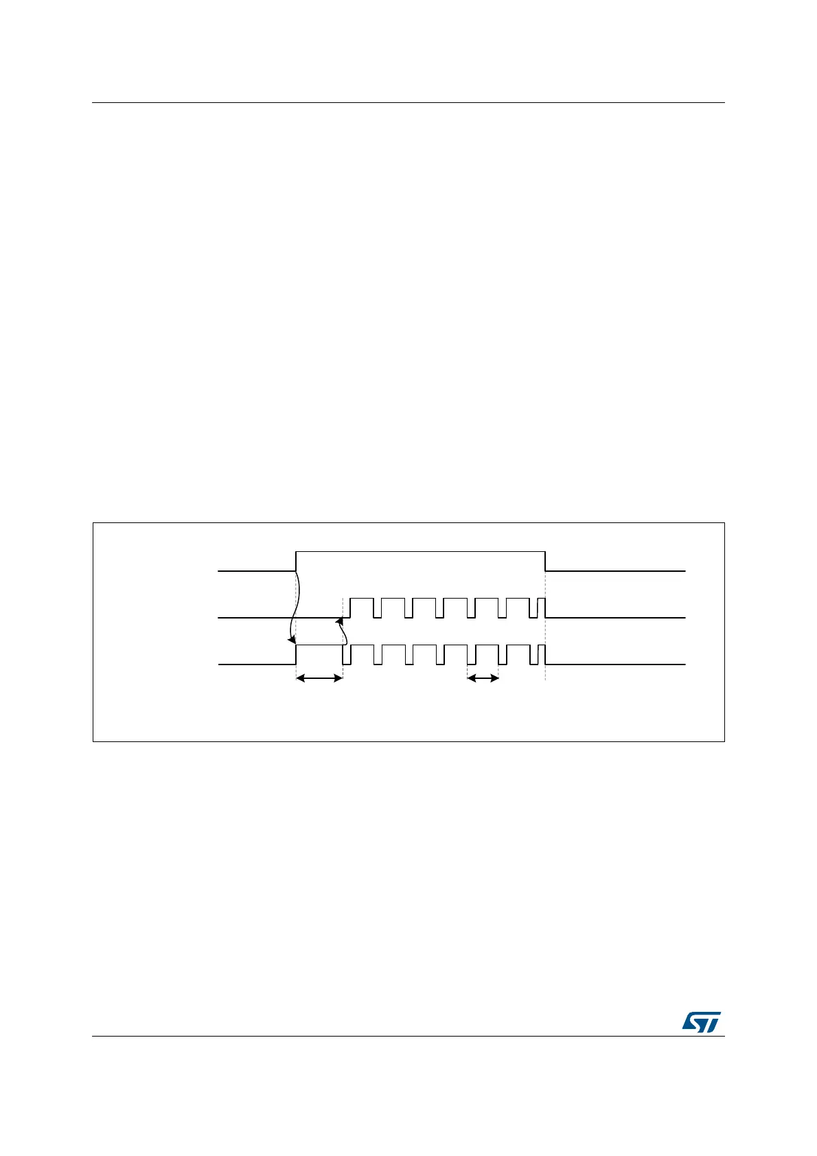
The chopper parameters can be adjusted using the HRIM_CHPxR register, with the
possibility to define a specific pulsewidth at the beginning of the pulse, to be followed by a
carrier frequency with programmable frequency and duty cycle, as in Figure 243.
CARFRQ[3:0] bits define the frequency, ranging from 664.06 kHz to 10.625 MHz (for
f
HRTIM
= 170 MHz) following the formula F
CHPFRQ
= f
HRTIM
/ (16 x (CARFRQ[3:0]+1)).
The duty cycle can be adjusted by 1/8 step with CARDTY[2:0], from 0/8 up to 7/8 duty cycle.
When CARDTY[2:0] = 000 (duty cycle = 0/8), the output waveform only contains the starting
pulse following the rising edge of the reference waveform, without any added carrier.
The pulsewidth of the initial pulse is defined using the STRPW[3:0] bitfield as follows:
t1STPW = (STRPW[3:0]+1) x 16 x t
HRTIM
and ranges from 94 ns to 1.51 µs (for
f
HRTIM
=170 MHz).
The carrier frequency parameters are defined based on the f
HRTIM
frequency, and are not
dependent from the CKPSC[2:0] setting.
In chopper mode, the carrier frequency and the initial pulsewidth are combined with the
reference waveform using an AND function. A synchronization is performed at the end of
the initial pulse to have a repetitive signal shape.
The chopping signal is stopped at the end of the output waveform active state, without
waiting for the current carrier period to be completed. It can thus contain shorter pulses than
programmed.
Figure 243. HRTIM outputs with Chopper mode enabled
Note: CHP1 and CHP2 bits must be set prior to the output enable done with TxyOEN bits in the
HRTIM_OENR register.
CARFRQ[2:0], CARDTY[2:0] and STRPW[3:0] bitfields cannot be modified while the
chopper mode is active (at least one of the two CHPx bits is set)
.
27.3.17 Fault protection
The HRTIM has a versatile fault protection circuitry to disable the outputs in case of an
abnormal operation. Once a fault has been triggered, the outputs take a predefined safe
state. This state is maintained until the output is re-enabled by software. In case of a
permanent fault request, the output remains in its fault state, even if the software attempts to
re-enable them, until the fault source disappears.
The HRTIM has 6 FAULT input channels; all of them are available and can be combined for
each of the 6 timing units, as shown on Figure 244.
MS32335V3
Start pulsewidth
HRTIM_CHx1
Output x1
Carrier
Carrier period
Start
 Loading...


