RM0440 Rev 4 273/2126
RM0440 Reset and clock control (RCC)
338
significant capacitive load. In case on an internal reset, the internal pull-up RPU is
deactivated in order to save the power consumption through the pull-up resistor. This
mode is always active (independently of the option bytes setting) during each device
power-on-reset (until option bytes are loaded): power on the device or wakeup from
Shutdown mode.
• Reset input
In this mode, any valid reset signal on the NRST pin is propagated to device internal
logic, but resets generated internally by the device are not visible on the pin. In this
configuration, GPIO functionality (PG10) is not available.
• GPIO
In this mode, the pin can be used as PG10 standard GPIO. The reset function of the
pin is not available. Reset is only possible from device internal reset sources and it is
not propagated to the pin.
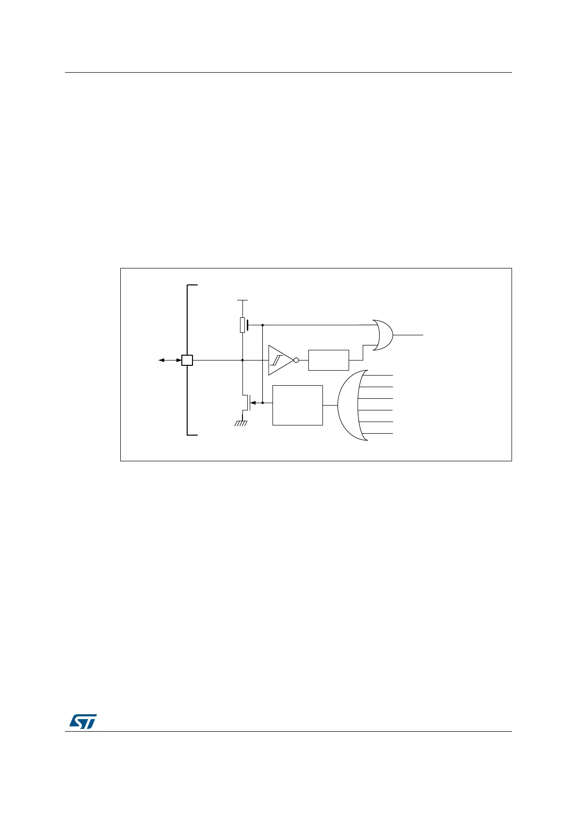
Figure 16. Simplified diagram of the reset circuit
Software reset
The SYSRESETREQ bit in Cortex
®
-M4 with FPU Application Interrupt and Reset Control
Register must be set to force a software reset on the device (refer to the
STM32F3xx/F4xx/L4xx Cortex
®
-M4 programming manual (PM0214)).
Low-power mode security reset
To prevent that critical applications mistakenly enter a low-power mode, two low-power
mode security resets are available. If enabled in option bytes, the resets are generated in
the following conditions:
MSv40966V2
External
reset
V
DD
R
PU
WWDG reset
Software reset
Low-power manager reset
IWDG reset
Option byte loader reset
Pulse
generator
(min 20 μs)
NRST
System reset
Filter
POR
 Loading...


