RM0440 Rev 4 497/2126
RM0440 Filter math accelerator (FMAC)
513
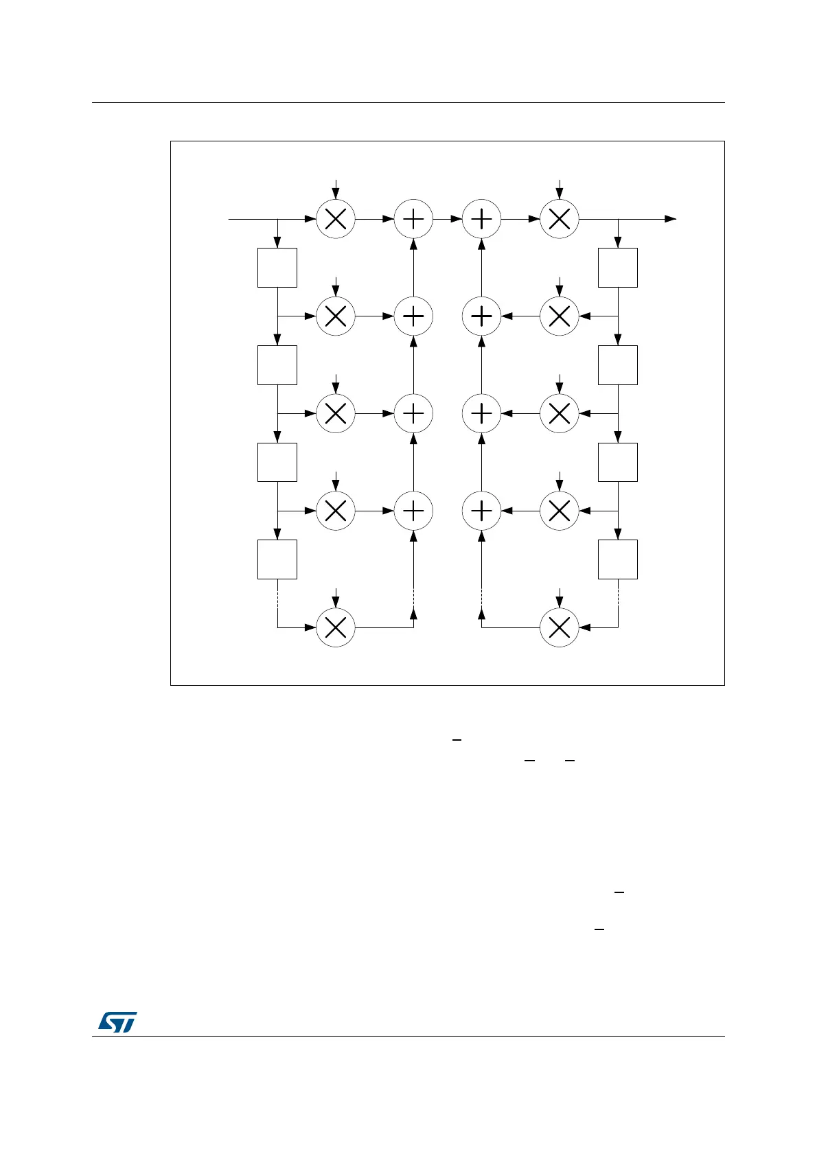
Figure 48. IIR filter structure (direct form 1)
Input:
• X1 buffer contains the elements of vector X. It is a circular buffer of length N + 1+ d.
• X2 buffer contains the elements of coefficient vectors B
and A concatenated
(b
0
, b
1
, b
2
..., b
N
, a
1
, a
2
, ..., a
M
). It is a fixed buffer of length M+N+1.
Output:
• Y buffer contains the output values, y
n
. It is a circular buffer of length M + d.
Parameters
• The parameter P contains the length, N + 1, of the coefficient vector B in the range
[2:64].
• The parameter Q contains the length, M, of the coefficient vector A
in the range [1:63].
• The parameter R contains the gain to be applied to the accumulator output. The value
output to the Y buffer is multiplied by 2
R
, where R is in the range [0:7].
a[1]
a[2]
a[3]
Z
-1
Z
-1
Z
-1
y[n]
y[n-1]
y[n-2]
Z
-1
x[n]
b[1]
x[n-1]
b[2]
Z
-1
b[3]
x[n-2]
Z
-1
b[0]
b[N]
Z
-1
x[n-3]
x[n-N]
Z
-1
a[M]
y[n-3]
y[n-M]
2
R
MSv47127V1
 Loading...


