Low-power timer (LPTIM) RM0440
1468/2126 RM0440 Rev 4
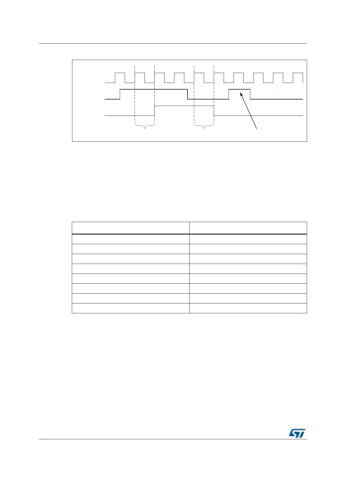
Figure 494. Glitch filter timing diagram
Note: In case no internal clock signal is provided, the digital filter must be deactivated by setting
the CKFLT and TRGFLT bits to ‘0’. In that case, an external analog filter may be used to
protect the LPTIM external inputs against glitches.
32.4.5 Prescaler
The LPTIM 16-bit counter is preceded by a configurable power-of-2 prescaler. The prescaler
division ratio is controlled by the PRESC[2:0] 3-bit field. The table below lists all the possible
division ratios:
32.4.6 Trigger multiplexer
The LPTIM counter may be started either by software or after the detection of an active
edge on one of the 13 trigger inputs.
TRIGEN[1:0] is used to determine the LPTIM trigger source:
• When TRIGEN[1:0] equals ‘00’, The LPTIM counter is started as soon as one of the
CNTSTRT or the SNGSTRT bits is set by software. The three remaining possible
values for the TRIGEN[1:0] are used to configure the active edge used by the trigger
inputs. The LPTIM counter starts as soon as an active edge is detected.
• When TRIGEN[1:0] is different than ‘00’, TRIGSEL[2:0] is used to select which of the
13 trigger inputs is used to start the counter.
MS32490V1
CLKMUX
Input
Filter out
2 consecutive samples 2 consecutive samples Filtered
Table 313. Prescaler division ratios
programming dividing factor
000 /1
001 /2
010 /4
011 /8
100 /16
101 /32
110 /64
111 /128
 Loading...


