High-resolution timer (HRTIM) RM0440
956/2126 RM0440 Rev 4
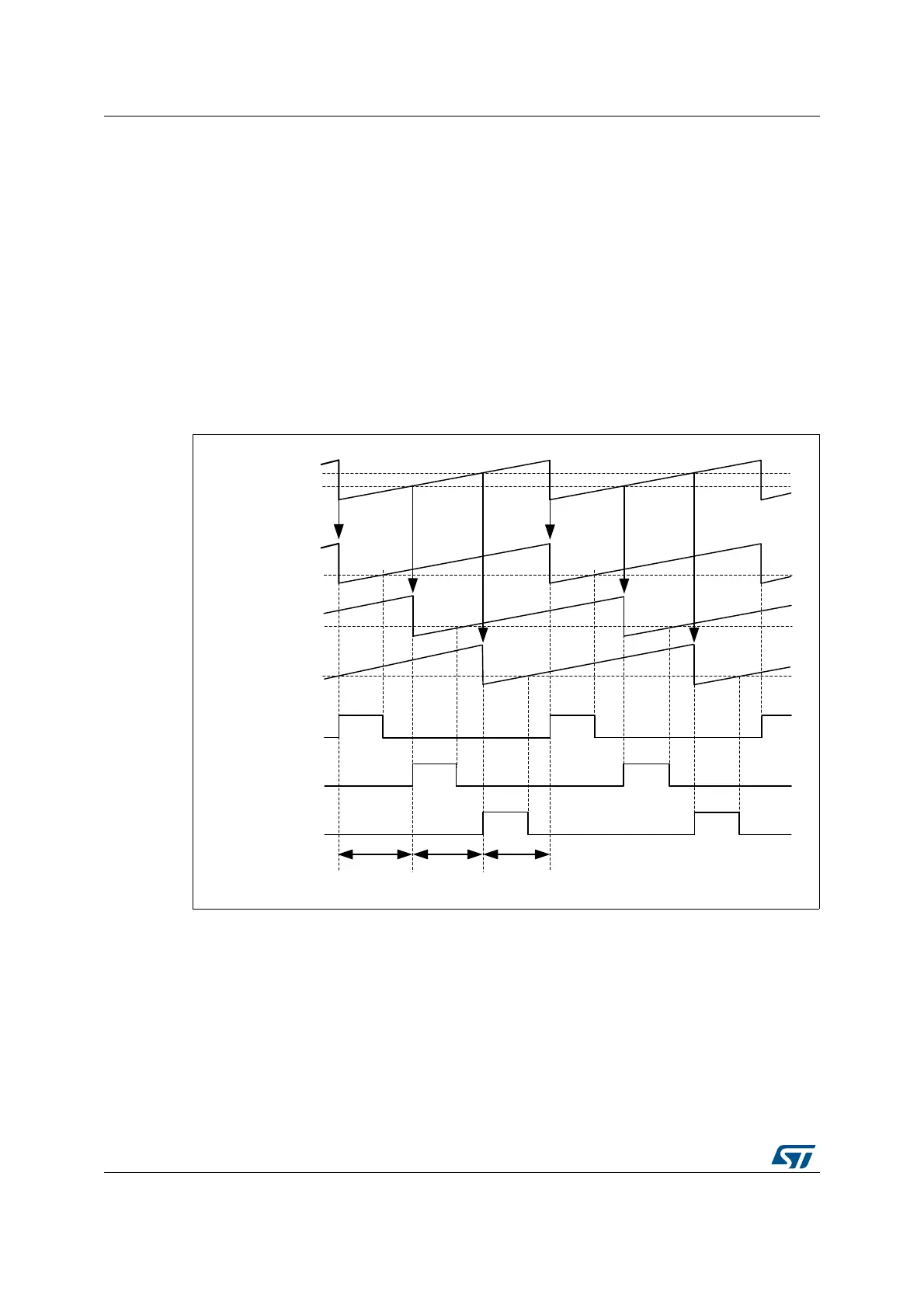
The master timer is responsible for the phase management: it defines the phase
relationship between the converters by resetting the timers periodically. The phase-shift is
360° divided by the number of phases, 120° in the given example.
The duty cycle is then programmed into each of the timers. The outputs are defined as
follows:
– HRTIM_CHA1 set on master timer period, reset on TACMP1
– HRTIM_CHB1 set on master timer MCMP1, reset on TBCMP1
– HRTIM_CHC1 set on master timer MCMP2, reset on TCCMP1
The ADC trigger can be generated on TxCMP2 compare event. Since all ADC trigger
sources are phase-shifted because of the converter topology, it is possible to have all of
them combined into a single ADC trigger to save ADC resources (for instance 1 ADC
regular channel for the full multi-phase converter).
Figure 266. 3-phase interleaved buck converter control
27.4.4 Transition mode power factor correction
The basic operating principle is to build up current into an inductor during a fixed Ton time.
This current then decays during the Toff time, and the period is re-started when it becomes
null. This is detected using a Zero Crossing Detection circuitry (ZCD), as shown on
Figure 267. With a constant Ton time, the peak current value in the inductor is proportional
to the rectified AC input voltage, which provides the power factor correction.
MS32348V2
120°120°120°
TIMA
counter
CMP1
TIMB
counter
TIMC
counter
CMP1
CMP1
CMP1
Master
counter
CMP2
Reset Reset Reset Reset Reset Reset
HRTIM_CHA1
HRTIM_CHB1
HRTIM_CHC1
 Loading...


