RM0440 Rev 4 1107/2126
RM0440 Advanced-control timers (TIM1/TIM8/TIM20)
1226
the output (typically to reset a PWM output for a current limitation), and as a trigger for the
Slave mode controller.
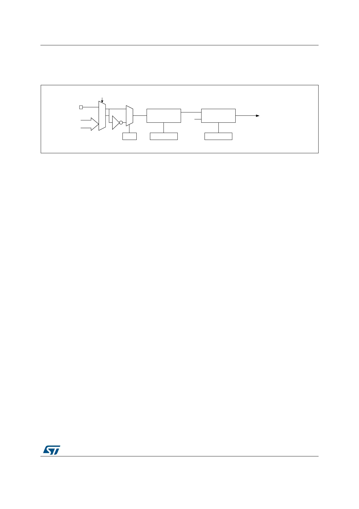
Figure 290. External trigger input block
The tim_etr_in input comes from multiple sources: input pins (default configuration), or
internal sources. The selection is done with the ETRSEL[3:0] bitfield in the TIMx_AF1
register.
Refer to Section 28.3.2: TIM1/TIM8/TIM20 pins and internal signals for the list of sources
connected to the etr_in input in the product.
28.3.7 Clock selection
The counter clock can be provided by the following clock sources:
• Internal clock (tim_ker_ck)
• External clock mode1: external input pin (tim_ti1 or tim_ti2)
• External clock mode2: external trigger input (tim_etr_in)
• Encoder mode
Internal clock source (tim_ker_ck)
If the slave mode controller is disabled (SMS=000), then the CEN, DIR (in the TIMx_CR1
register) and UG bits (in the TIMx_EGR register) are actual control bits and can be changed
only by software (except UG which remains cleared automatically). As soon as the CEN bit
is written to 1, the prescaler is clocked by the internal clock tim_ker_ck.
Figure 291 shows the behavior of the control circuit and the upcounter in normal mode,
without prescaler.
MSv62316V1
To the Output mode controller
To the CK_PSC circuitry
To the Slave mode controller
0
1
tim_etr[1..15]
tim_etr_in
ETP
TIMx_SMCR
Divider
/1, /2, /4, /8
ETPS[1:0]
TIMx_SMCR
Filter
downcounter
ETF[3:0]
TIMx_SMCR
tim_etrp
f
DTS
tim_etrf
TIM_ETR
(tim_etr0)
TIMx_AF1[17:14]
(1)
 Loading...


