High-resolution timer (HRTIM) RM0440
862/2126 RM0440 Rev 4
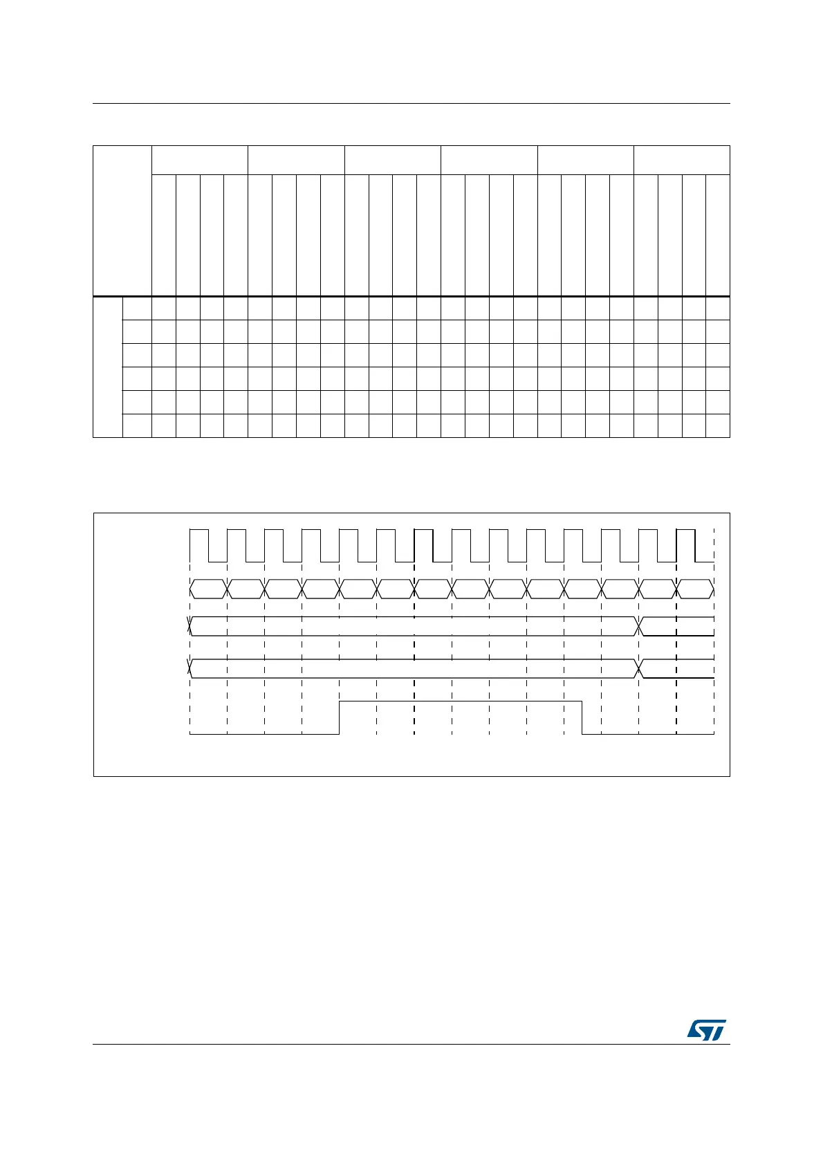
Figure 190 represents how a PWM signal is generated using two compare events.
Figure 190. Compare events action on outputs: set on compare 1, reset on compare 2
Set / reset on update events
A set or reset event on update is done at low resolution. When CKPSC[2:0] < 5, the high-
resolution delay is set to its maximum value so that a set/reset event on update always lags
as compared to other compare set/reset events, with a jitter varying between 0 and 31/32 of
a f
HRTIM
clock period.
Half mode
This mode aims at generating square signal with fixed 50% duty cycle and variable
frequency (typically for converters using resonant topologies). It allows to have the duty
cycle automatically forced to half of the period value when a new period is programmed.
Table 216. Events mapping across timer A to F
Source
Timer A Timer B Timer C Timer D Timer E Timer F
CMP1
CMP2
CMP3
CMP4
CMP1
CMP2
CMP3
CMP4
CMP1
CMP2
CMP3
CMP4
CMP1
CMP2
CMP3
CMP4
CMP1
CMP2
CMP3
CMP4
CMP1
CMP2
CMP3
CMP4
Destination
TA----12---34-56----78---9
TB12--------34--5678----9-
TC-12- -34- -- - - -5-6--78-9--
TD1- -2-3-4-- -5- -- -6- -78-9-
TE---1--2345--67--------89
TF--1-2- -34- -5--67-89- - -- -
MS32264V2
f
HRTIM
HRTIM_CHA1
00
Counter
Clock
Register setting: HRTIM_SETA1R = 0x0000 0008, HRTIM_RSTA1R = 0x0000 0010
HRTIM_CMP1AR = 0x0000 0080
HRTIM_CMP2AR = 0x0000 0150
Output
CMP registers
(value is updated
when counter
rolls-over)
20
40 60 80 A0 C0 E0 100 120 140 160 00 20