RM0440 Rev 4 871/2126
RM0440 High-resolution timer (HRTIM)
1083
Note: In triggered half mode, the compare2 register is controlled by hardware and writing it has no
effect. However the written value is stored in the preload register and becomes active on the
update event following the exit of this mode.
Push-pull mode
This mode primarily aims at driving converters using push-pull topologies. It also needs to
be enabled when the delayed idle protection is required, typically for resonant converters
(refer to Section 27.3.10: Delayed protection).
The push-pull mode is enabled by setting PSHPLL bit in the HRTIM_TIMxCR register.
It applies the signals generated by the crossbar to output 1 and output 2 alternatively, on the
period basis, maintaining the other output to its inactive state. The redirection rate (push-pull
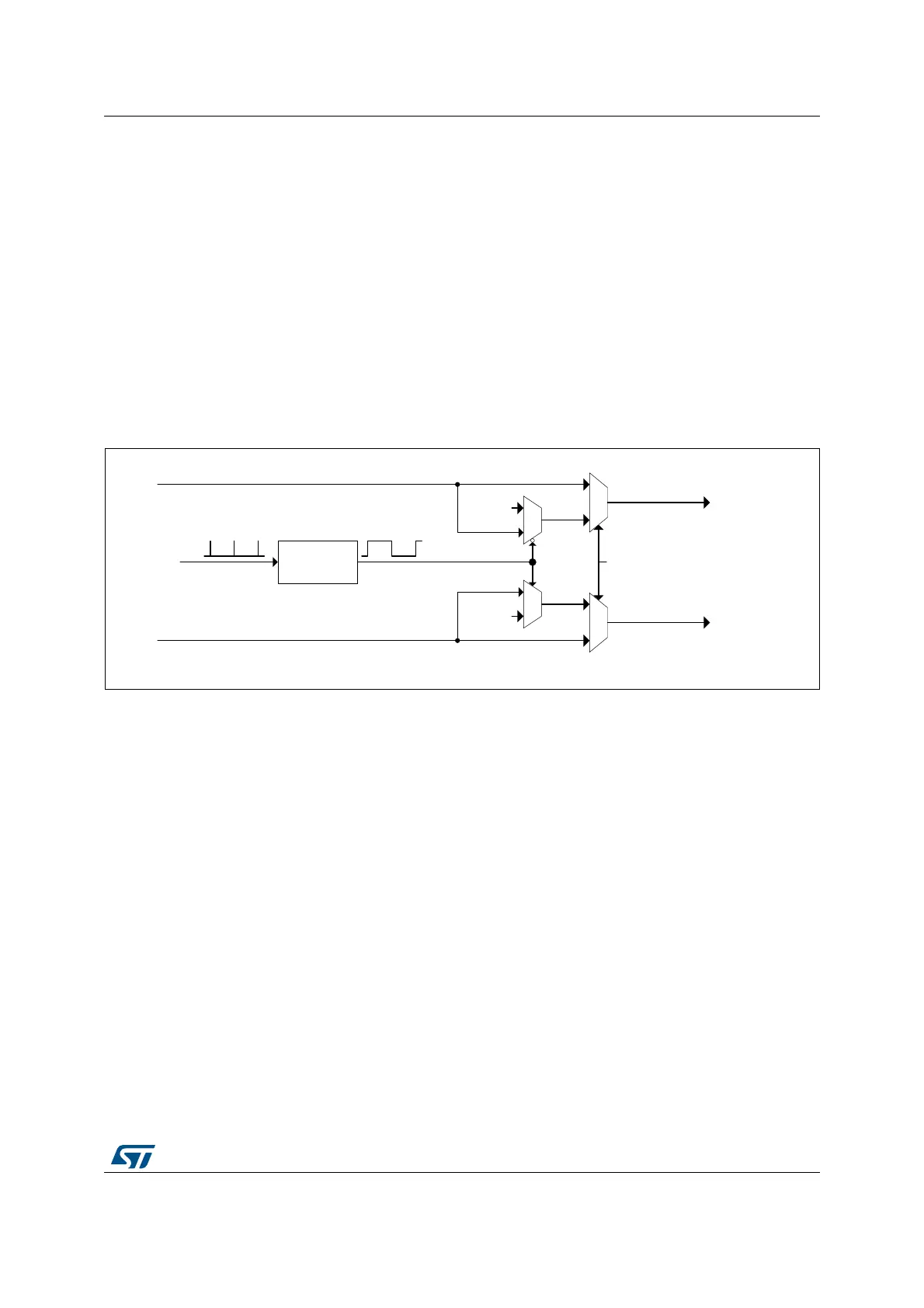
frequency) is defined by the timer’s period event, as shown on Figure 195. The push-pull
period is twice the timer counting period.
Figure 195. Push-pull mode block diagram
The push-pull mode is available when the timer operates in continuous mode and in single-
shot mode. It is necessary to disable the timer to stop a push-pull operation and to reset the
counter before re-enabling it.
To get a correct behavior, the event selected as source of the counter reset must be also
selected for setting (or resetting) the output. It must set the output if the output is set on
period, else it must reset it. If it is not done, the output switching from its inactive period to its
active period may be incorrect (may unexpectedly rise or may unexpectedly stay low).
The signal shape is defined using HRTIM_SETxyR and HRTIM_RSTxyR for both outputs. It
is necessary to have HRTIM_SETx1R = HRTIM_SETx2R and HRTIM_RSTx1R =
HRTIM_RSTx2R to have both outputs with identical waveforms and to achieve a balanced
operation. Still, it is possible to have different programming on both outputs for other uses.
The CPPSAT status bit in HRTIM_TIMxISR indicates on which output the signal is currently
active. CPPSTAT is reset when the push-pull mode is disabled.
In the example given on Figure 196, the timer internal waveform is defined as follows:
• Output set on period event
• Output reset on compare 1 match event
MS32268V1
Out 1
Out 2
To the
output
stage
Out 1 (from crosssbar)
Inactive
0
1
0
1
Push-Pull
logic
Roll-over
events
1
0
0
1
PSHPLL
Out 2 (from crosssbar)
Inactive
 Loading...


