USB Type-C™ / USB Power Delivery interface (UCPD) RM0440
2044/2126 RM0440 Rev 4
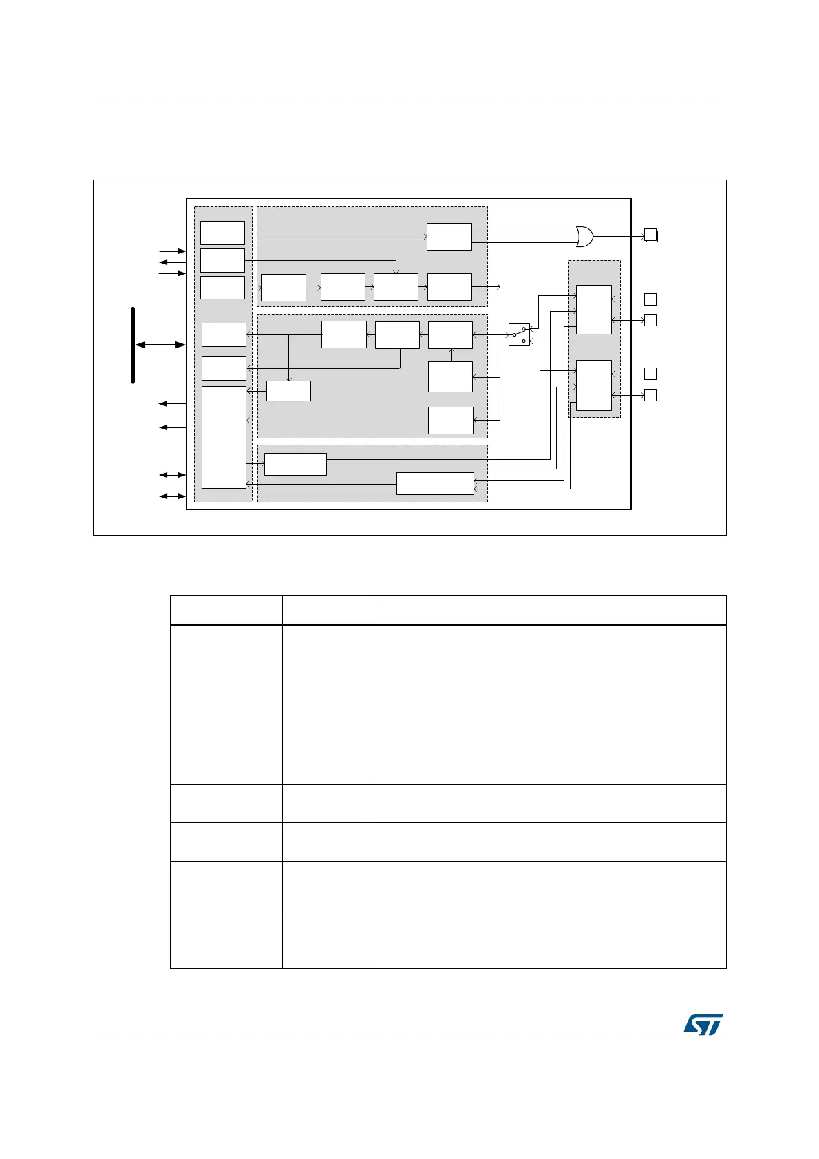
46.4.1 UCPD block diagram
Figure 673. UCPD block diagram
The following table lists external signals (alternate or additional I/O functions).
MSv45535V2
Analog
PHY
UCPD
Registers
4b5b
encode
4b5b
decode
Ordered
set insert
BMC
frequency
estimate
Tx byte
register
Rx byte
register
Tx ordered
set register
Rx ordered
set register
BMC
decode
Ordered
set detect /
filter
BMC
encode
CRC add
CRC
check
FRS
(pulse)
FRS
(detect)
Status
register
(interrupts/
events)
Type-C debounce
CC1 + CC2
Control
register
Type-C control
CC1 + CC2
UCPDx_FRSTX
UCPDx_DBCC1
UCPDx_DBCC2
UCPDx_CC1
UCPDx_CC2
32-bit APB bus
To NVIC:
ucpd_it
To EXTI:
ucpd_wkup
Ch. 1
Ch. 2
To/from RCC:
ucpd_ker_ck
clk_rq
ucpd_pclk
To/from DMA:
Alternate or
additional
I/O function
Power Delivery Tx
(CC1 or CC2)
Power Delivery Rx
(CC1 or CC2)
Type-C controller (CC1 and CC2)
Ch.1
Ch.2
ucpd_tx_dma
ucpd_rx_dma
Table 419. UCPD signals on pins
Pin name Signal type Description
UCPDx_FRSTX Output
USB Type-C fast role swap (FRS) signaling control, applicable
to DRPs only. The signal (active high) drives an external NMOS
transistor that pulls down the active CC line. A typical
application has two such transistors (one per CC line) and
reserves a separate I/O to drive either NMOS. Initially, the I/Os
are configured as low-driving GPIOs. Upon detecting, through
the Type-C state machine, the orientation of the cable attached,
which determines the active CC line, the I/O of the active CC
line must be set to its UCPDx_FRSTX alternate function and
the I/O of the inactive CC line as low-driving GPIO.
UCPDx_CC1 Input/output
USB Type-C configuration control line 1, to be routed to the
USB Type-C connector CC1 terminal.
UCPDx_CC2 Input/output
USB Type-C configuration control line 2, to be routed to the
USB Type-C connector CC2 terminal.
UCPDx_DBCC1 Input
USB Type-C configuration control line 1 dead battery signal, to
be routed to the USB Type-C connector CC1 terminal if dead
battery support is required.
UCPDx_DBCC2 Input
USB Type-C configuration control line 2 dead battery signal, to
be routed to the USB Type-C connector CC2 terminal if dead
battery support is required.
 Loading...


