Advanced-control timers (TIM1/TIM8/TIM20) RM0440
1110/2126 RM0440 Rev 4
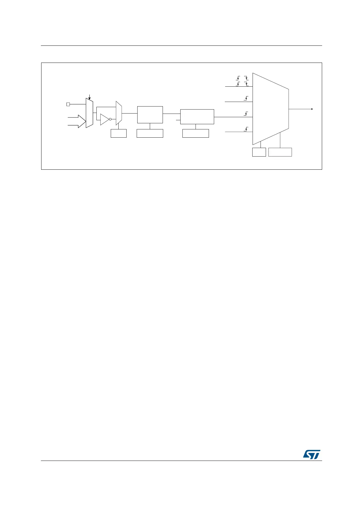
Figure 294. External trigger input block
1. Refer to Section 28.3.2: TIM1/TIM8/TIM20 pins and internal signals.
For example, to configure the upcounter to count each 2 rising edges on tim_etr_in, use the
following procedure:
1. As no filter is needed in this example, write ETF[3:0]=0000 in the TIMx_SMCR register.
2. Set the prescaler by writing ETPS[1:0]=01 in the TIMx_SMCR register
3. Select rising edge detection on the tim_etr_in input by writing ETP=0 in the
TIMx_SMCR register
4. Enable external clock mode 2 by writing ECE=1 in the TIMx_SMCR register.
5. Enable the counter by writing CEN=1 in the TIMx_CR1 register.
The counter counts once each 2 tim_etr_in rising edges.
The delay between the rising edge on tim_etr_in and the actual clock of the counter is due
to the resynchronization circuit on the tim_etrp signal. As a consequence, the maximum
frequency which can be correctly captured by the counter is at most ¼ of tim_ker_ck
frequency. When the ETRP signal is faster, the user should apply a division of the external
signal by a proper ETPS prescaler setting.
MSv62320V1
0
1
TIMx_SMCR
TIM_ETR
(tim_etr0)
tim_etr_in
Filter
downcounter
f
DTS
tim_etrp
TIMx_SMCR
ETPS[1:0]
TIMx_SMCR
ETF[3:0]
TIMx_AF1[17:14]
Divider
/1, /2, /4, /8
ETP
External clock
mode 1
Internal clock
mode
tim_psc_ck
TIMx_SMCR
SMS[2:0]
(internal clock)
Encoder
mode
External clock
mode 2
ECE
tim_trgi
tim_etrf
tim_ker_ck
tim_ti2f or
tim_ti1f or
or
tim_etr[1..15]
(1)
 Loading...


