Advanced-control timers (TIM1/TIM8/TIM20) RM0440
1160/2126 RM0440 Rev 4
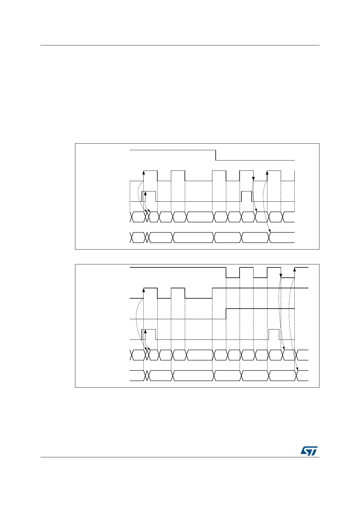
Index management in non-quadrature mode
The Figure 346 and Figure 347 below detail how the index is managed in directional clock
mode and clock plus direction mode, when the SMS[3:0] bitfield is equal to 1010, 1011,
1100, 1101.
For both of these modes, the index sensitivity is set with the IPOS[0] bit as following:
• IPOS[0] = 0: Index is detected on clock low level
• IPOS[0] = 1: Index is detected on clock high level
The IPOS[1] bit is not-significant.
Figure 346. Index behavior in clock + direction mode, IPOS[0] = 1
Figure 347. Index behavior in directional clock mode, IPOS[0] = 1
Encoder error management
For encoder configurations where 2 quadrature signals are available, it is possible to detect
transition errors. The reading on the 2 inputs corresponds to a 2-bit gray code which can be
represented as a state diagram, on the Figure 348. below. A single bit is expected to change
at once. An erroneous transition will set the TERRF interrupt flag in the TIMx_SR status
MSv62355V1
tim_ti1
tim_ti2
Index
Counter x2 mode
Counter x1 mode
321 34 72 6 5
2 1
7
1
7 0
7 0
MSv62356V1
DIR bit
Counter x2 mode
Counter x1 mode
321 34 12 0 8
2 1
9
1
9 0
0
9
0
9
tim_ti1
tim_ti2
 Loading...


