RM0440 Rev 4 873/2126
RM0440 High-resolution timer (HRTIM)
1083
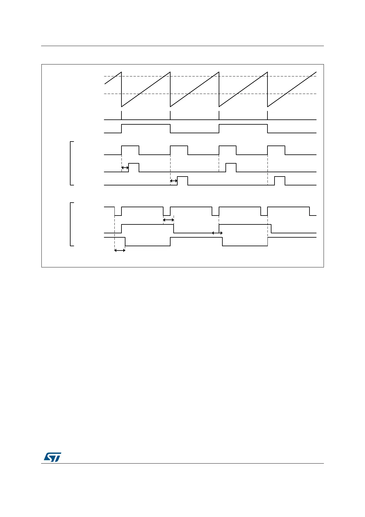
Figure 197. Push-Pull with deadtime
Deadtime
A deadtime insertion unit allows to generate a couple of complementary signals from a
single reference waveform, with programmable delays between active state transitions. This
is commonly used for topologies using half-bridges or full bridges. It simplifies the software:
only 1 waveform is programmed and controlled to drive two outputs.
The Dead time insertion is enabled by setting DTEN bit in HRTIM_OUTxR register. The
complementary signals are built based on the reference waveform defined for output 1,
using HRTIM_SETx1R and HRTIM_RSTx1R registers: HRTIM_SETx2R and
HRTIM_RSTx2R registers are not significant when DTEN bit is set.
Two deadtimes can be defined in relationship with the rising edge and the falling edge of the
reference waveform, as in Figure 198.
MSv48356V2
Push-Pull
logic
Crossbar
output
HRTIM_CHx1
HRTIM_CHx2
Roll-over
events
Compare 1
Deadtime
rising
Compare 2
Deadtime
falling
Crossbar
output
Negative
Deadtime
rising
Negative
Deadtime falling
Set on
Period
Reset
on
CMP1
Set on
Period
Reset
on
CMP2
HRTIM_CHx1
HRTIM_CHx2
 Loading...


