RM0440 Rev 4 921/2126
RM0440 High-resolution timer (HRTIM)
1083
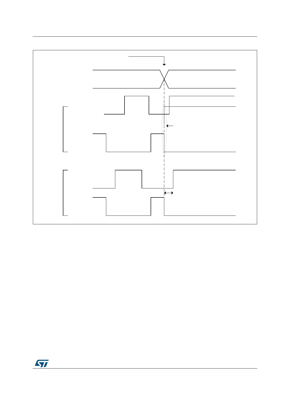
Figure 238. Delayed burst mode entry with deadtime enabled and IDLESx = 1
The delayed burst entry mode is enabled with DIDLx bit in the HRTIM_OUTxR register (one
enable bit per output). It forces a deadtime insertion before the output takes its idle state.
Each TIMx output has its own deadtime value:
– DTRx[8:0] on output 1 when DIDL1 = 1
– DTFx[8:0] on output 2 when DIDL2 = 1
DIDLx bits can be set only if one of the outputs has an active idle level during the burst
mode (IDLES = 1) and only when positive deadtimes are used (SDTR/SDTF set to 0).
Note: The delayed burst entry mode uses deadtime generator resources. Consequently, when any
of the 2 DIDLx bits is set and the corresponding timing unit uses the deadtime insertion
(DTEN bit set in HRTIM_OUTxR), it is not possible to use the timerx output 2 as a filter for
external events (Tx2 filtering signal is not available).
When durations defined by DTRx[8:0] and DTFx[8:0] are lower than 3 f
HRTIM
clock cycle
periods, the limitations related to the narrow pulse management listed in Section 27.3.7
must be applied.
When the burst mode entry arrives during the regular deadtime, it is aborted and a new
deadtime is re-started corresponding to the inactive period, as on Figure 239.
MS32285V2
RUN IDLE
Burst Trigger
Delayed idle
state
HRTIM_CHx1
IDLES1 = 1
HRTIM_CHx2
IDLES2 = 0
Output State
HRTIM_CHx1
IDLES1 = 1
HRTIM_CHx2
IDLES2 = 0
DIDL1 = 0
DIDL2 = 0
DIDL1 = 1
DIDL2 = 1
Deadtime
violation
 Loading...


