RM0440 Rev 4 2105/2126
RM0440 Debug support (DBG)
2112
47.17 TPIU (trace port interface unit)
47.17.1 Introduction
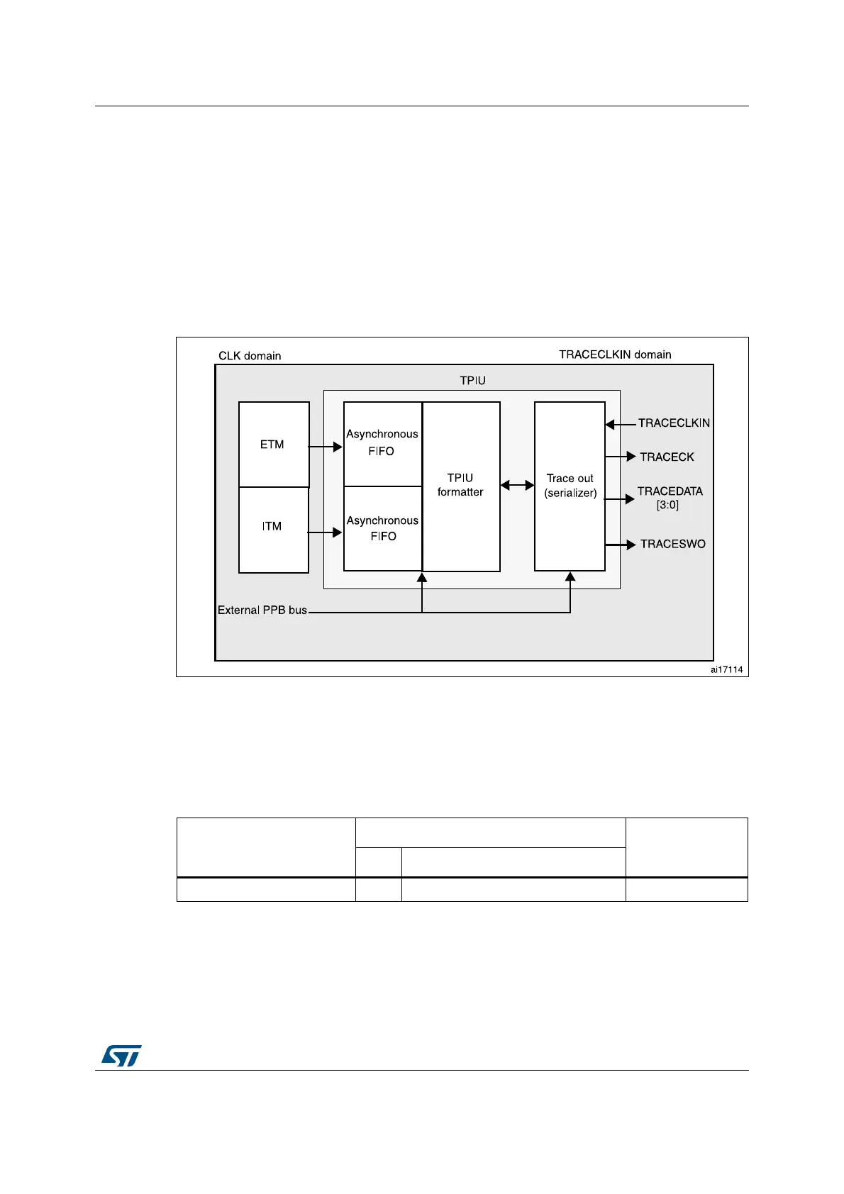
The TPIU acts as a bridge between the on-chip trace data from the ITM and the ETM.
The output data stream encapsulates the trace source ID, that is then captured by a trace
port analyzer (TPA).
The core embeds a simple TPIU, especially designed for low-cost debug (consisting of a
special version of the CoreSight TPIU).
Figure 687. TPIU block diagram
47.17.2 TRACE pin assignment
• Asynchronous mode
The asynchronous mode requires 1 extra pin and is available on all packages. It is only
available if using Serial Wire mode (not in JTAG mode).
• Synchronous mode
The synchronous mode requires from 2 to 6 extra pins depending on the data trace
size and is only available in the larger packages. In addition it is available in JTAG
mode and in Serial Wire mode and provides better bandwidth output capabilities than
asynchronous trace.
Table 442. Asynchronous TRACE pin assignment
TPUI pin name
Trace synchronous mode
STM32G4 Series
pin assignment
Type Description
TRACESWO O TRACE Asynchronous Data Output PB3
 Loading...


