RM0440 Rev 4 1111/2126
RM0440 Advanced-control timers (TIM1/TIM8/TIM20)
1226
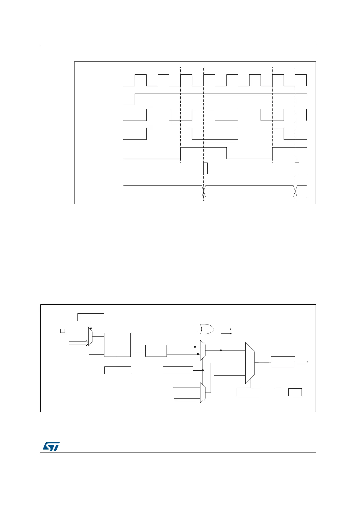
Figure 295. Control circuit in external clock mode 2
28.3.8 Capture/compare channels
Each capture/compare channel is built around a capture/compare register (including a
shadow register), an input stage for capture (with digital filter, multiplexing, and prescaler,
except for channels 5 and 6) and an output stage (with comparator and output control).
Figure 296 to Figure 299 give an overview of one capture/compare channel.
The input stage samples the corresponding tim_tix input to generate a filtered signal
tim_tixf. Then, an edge detector with polarity selection generates a signal (tim_tixfpy) which
can be used as trigger input by the slave mode controller or as the capture command. It is
prescaled before the capture register (ICxPS).
Figure 296. Capture/compare channel (example: channel 1 input stage)
The output stage generates an intermediate waveform which is then used for reference:
tim_ocxref (active high). The polarity acts at the end of the chain.
MSv62321V1
34 35 36
tim_ker_ck
CEN
tim_etr_in
tim_etrp
tim_etrf
tim_cnt_ck
tim_psc_ck
Counter register
MSv62322V1
0
1
ICPS[1:0]
tim_ti1f_ed
To the slave mode controller
tim_ti1_fp1
11
01
CC1S[1:0]
tim_ic1
tim_ti2fp1
tim_trc
(from slave mode
controller)
10
tim_ic1f
0
1
TIMx_CCER
CC1P/CC1NP
TIMx_CCMR1
Edge
detector
tim_ti1f_rising
tim_ti1f_falling
Filter
downcounter
ICF[3:0]
Divider
/1, /2, /4, /8
TIMx_CCMR1
TIMx_CCER
tim_ti2f_rising
(from channel 2)
tim_ti2f_falling
(from channel 2)
tim_ti1f
f
DTS
CC1E
TIM_CH1
tim_ti1_in[15..1]
tim_ti1_in0
TIMx_TISEL
TI1SEL[3:0]
 Loading...


