RM0440 Rev 4 1169/2126
RM0440 Advanced-control timers (TIM1/TIM8/TIM20)
1226
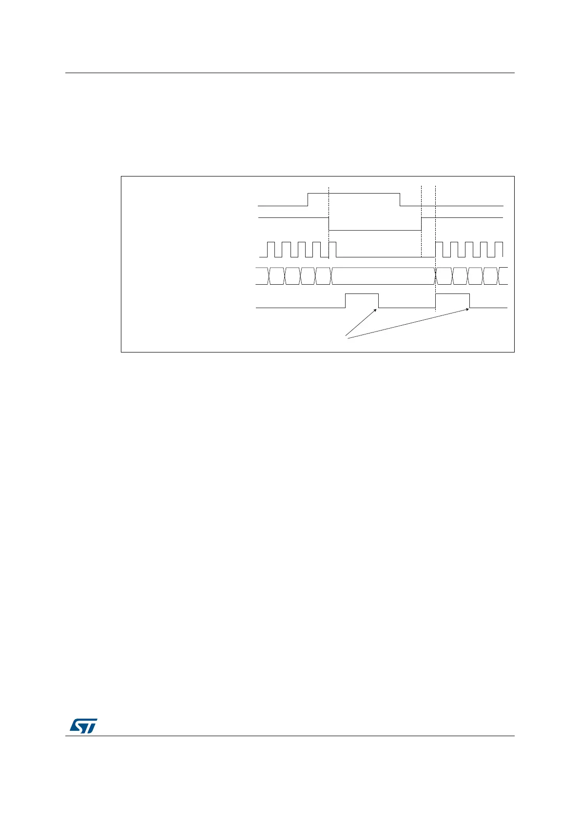
The counter starts counting on the internal clock as long as tim_ti1 is low and stops as soon
as tim_ti1 becomes high. The TIF flag in the TIMx_SR register is set both when the counter
starts or stops.
The delay between the rising edge on tim_ti1 and the actual stop of the counter is due to the
resynchronization circuit on tim_ti1 input.
Figure 355. Control circuit in Gated mode
Slave mode: Trigger mode
The counter can start in response to an event on a selected input.
In the following example, the upcounter starts in response to a rising edge on tim_ti2 input:
• Configure the channel 2 to detect rising edges on tim_ti2. Configure the input filter
duration (in this example, we do not need any filter, so we keep IC2F=0000). The
capture prescaler is not used for triggering, so it does not need to be configured. The
CC2S bits are configured to select the input capture source only, CC2S=01 in
TIMx_CCMR1 register. Write CC2P=1 and CC2NP=0 in TIMx_CCER register to
validate the polarity (and detect low level only).
• Configure the timer in trigger mode by writing SMS=110 in TIMx_SMCR register. Select
tim_ti2 as the input source by writing TS=00110 in TIMx_SMCR register.
When a rising edge occurs on tim_ti2, the counter starts counting on the internal clock and
the TIF flag is set.
The delay between the rising edge on tim_ti2 and the actual start of the counter is due to the
resynchronization circuit on tim_ti2 input.
MSv62362V1
37
tim_cnt_ck, tim_psc_ck
Counter register
38
32 33
34
35 36
3130
TIF
tim_ti1
CEN
Write TIF = 0
 Loading...


