RM0440 Rev 4 1151/2126
RM0440 Advanced-control timers (TIM1/TIM8/TIM20)
1226
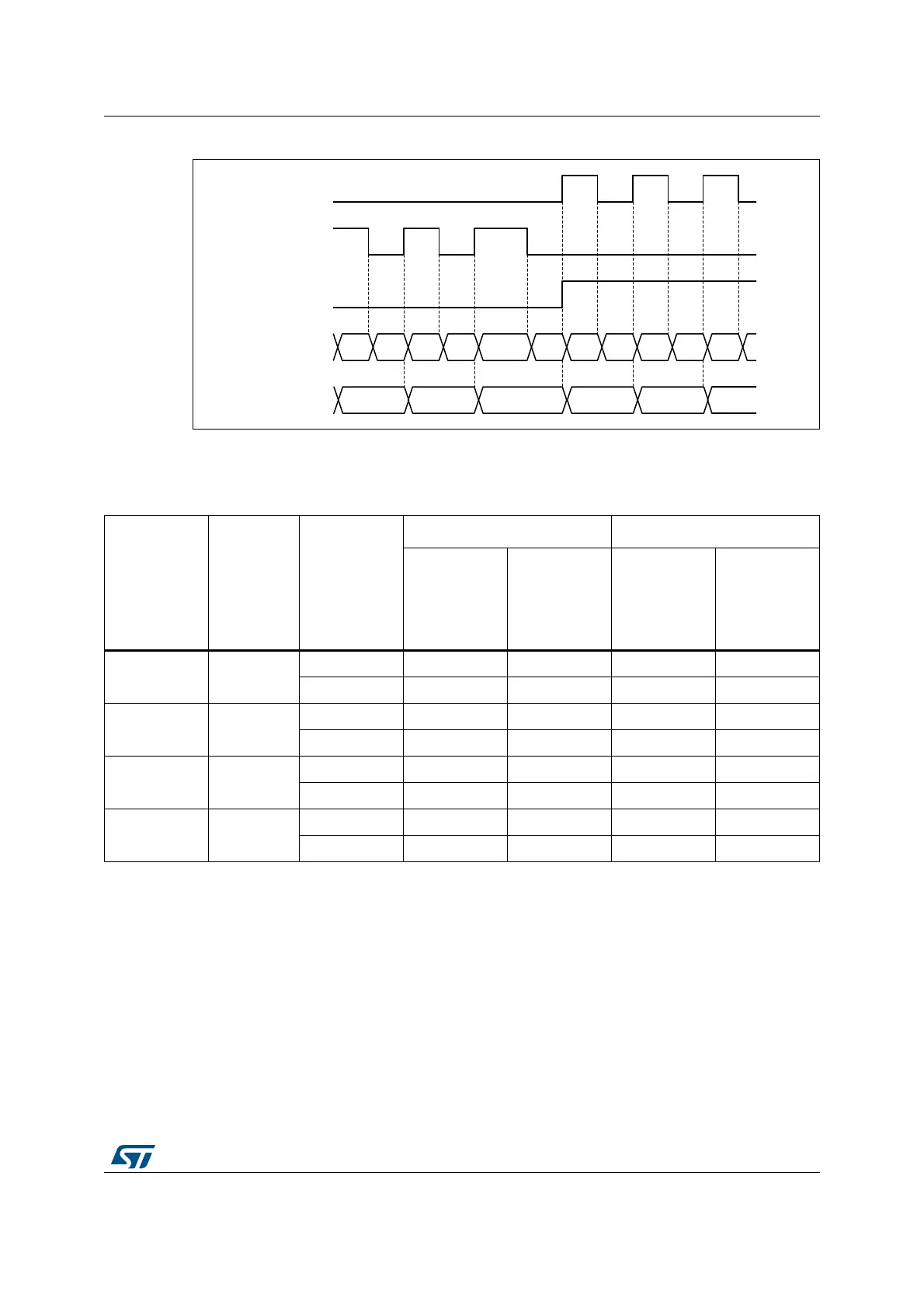
Figure 334. Directional clock encoder mode (CC1P = CC2P = 1)
The Table 261 here-below details how the directional clock mode operates, for any input
transition.
Index Input
The counter can be reset by an index signal coming from the encoder, indicating an
absolute reference position. The Index signal must be connected to the tim_etr_in input. It
can be filtered using the digital input filter.
The index functionality is enabled with the IE bit in the TIMX_ECR register. The IE bit must
be set only in encoder mode, when the SMS[3:0] bitfield has the following values: 0001,
0010, 011, 1010, 1011, 1100, 1101, 1110, 1111.
MSv62354V1
DIR bit
Counter x2 mode
Counter x1 mode
7 8 869 7
tim_ti2
tim_ti1
58 9 11 10 9 8 77 106 6
Table 261. Counting direction versus encoder signals and polarity settings
Directional
clock mode
SMS[3:0]
Level on
opposite
signal
(tim_ti1fp1 for
tim_ti2,
tim_ti2fp2 for
tim_ti1)
tim_ti1fp1 signal tim_ti2fp2 signal
Rising Falling Rising Falling
x2 mode
CCxP=0
1100
High Down Down Up Up
Low No count No count No count No count
x2 mode
CCxP=1
1100
High No count No count No count No count
Low Down Down Up Up
x1 mode
CCxP=0
1101
High No count Down No count Up
Low No count No count No count No count
x1 mode
CCxP=1
1101
High No count No count No count No count
Low Down No count Up No count
 Loading...


