High-resolution timer (HRTIM) RM0440
932/2126 RM0440 Rev 4
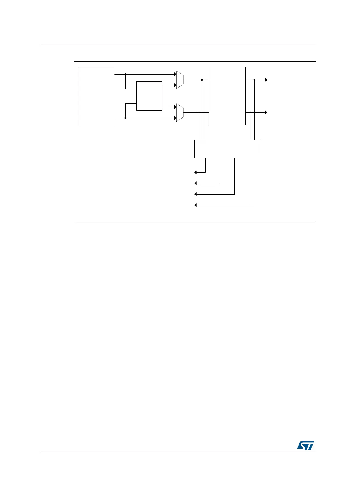
Figure 247. Auxiliary outputs
By default, the auxiliary outputs are copies of outputs Tx1 and Tx2. The exceptions are:
• The delayed idle and the balanced idle protections, when the deadtime is disabled
(DTEN = 0). When the protection is triggered, the auxiliary outputs are maintained and
follow the signal coming out of the crossbar. On the contrary, if the deadtime is enabled
(DTEN = 1), both main and auxiliary outputs are forced to an inactive level.
• The burst mode (TCEN=1, IDLEMx=1); there are 2 cases:
a) If DTEN=0 or DIDLx=0, the auxiliary outputs are not affected by the burst mode
entry and continue to follow the reference signal coming out of the crossbar (see
Figure 248).
b) If the deadtime is enabled (DTEN=1) together with the delayed burst mode entry
(DIDLx=1), the auxiliary outputs have the same behavior as the main outputs.
They are forced to the IDLES level after a deadtime duration, then they keep this
level during all the burst period. When the burst mode is terminated, the IDLES
level is maintained until a transition occurs to the opposite level, similarly to the
main output.
MS32290V2
Set / reset
crossbar with
events ORing
Push-pull
or
deadtime
insertion
Out 1
Out 2
HRTIM_CHx1
HRTIM_CHx2
To the
output
stage
Burst mode
controller
Auxiliary output circuitry
SETxy / RSTxy flags
Interrupts and DMA requests
Capture triggers
External event filtering
(Out 2 channel only)
 Loading...


