RM0440 Rev 4 903/2126
RM0440 High-resolution timer (HRTIM)
1083
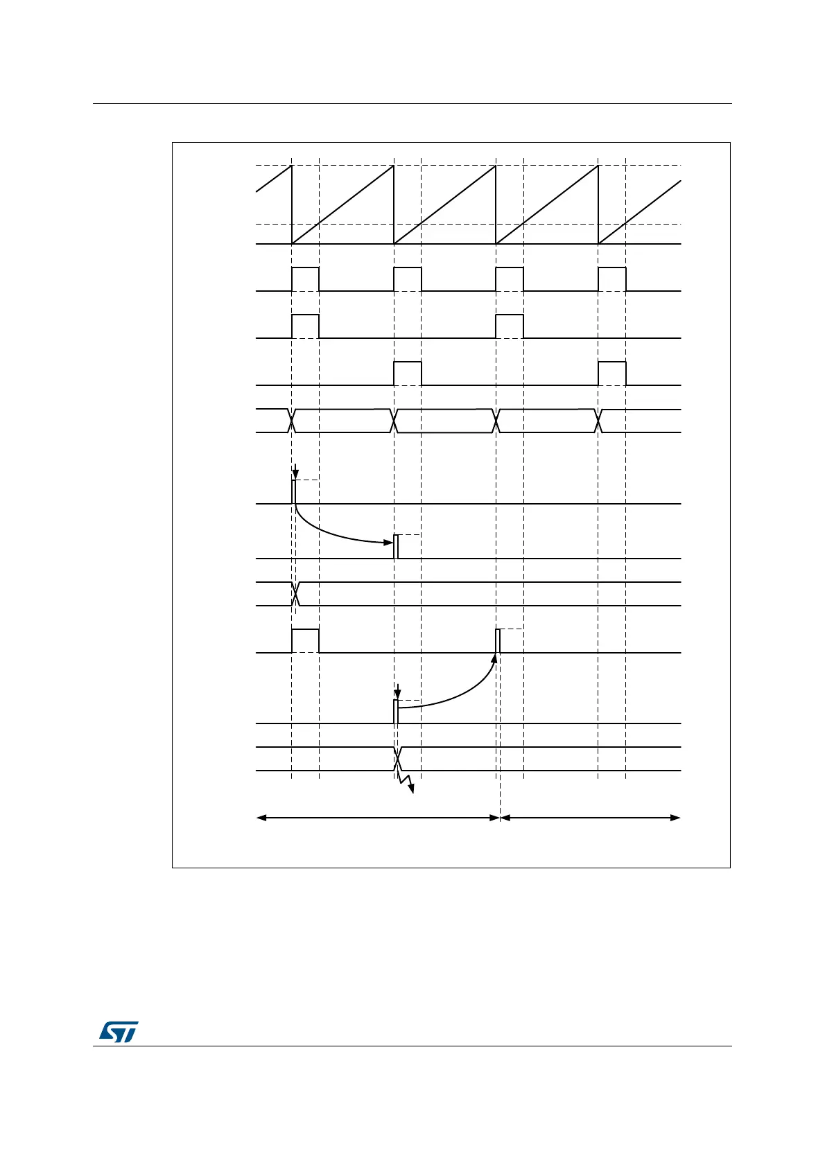
Figure 231. Balanced Idle protection example
When the balanced Idle mode is enabled, the selected external event triggers a capture of
the counter value into the compare 4 active register (this value is not user-accessible). The
push-pull is maintained for one additional period so that the shorten pulse can be repeated:
a new output reset event is generated while the regular output set event is maintained.
The Idle mode is then entered and the output takes the level defined by IDLESx bits in the
HRTIM_OUTxR register. The balanced idle mode entry is indicated by the DLYPRT flag,
MSv50809V1
CPPSTAT = 1CPPSTAT = 0 CPPSTAT = 0
CPPSTAT = 1
HRTIM_CHx2
HRTIM_CHx1
Taref
(internal)
CMP1
PER
counter
EEV
Pulse length
copied
IPPSTAT = 0
HRTIM_CHx1
HRTIM_CHx2
EEV
Pulse length
copied
IPPSTAT = 0 (reset value)
IPPSTAT = 1
DLYPRT
Run mode Idle mode
HRTIM_CHx1
HRTIM_CHx2
 Loading...


