Serial audio interface (SAI) RM0440
1838/2126 RM0440 Rev 4
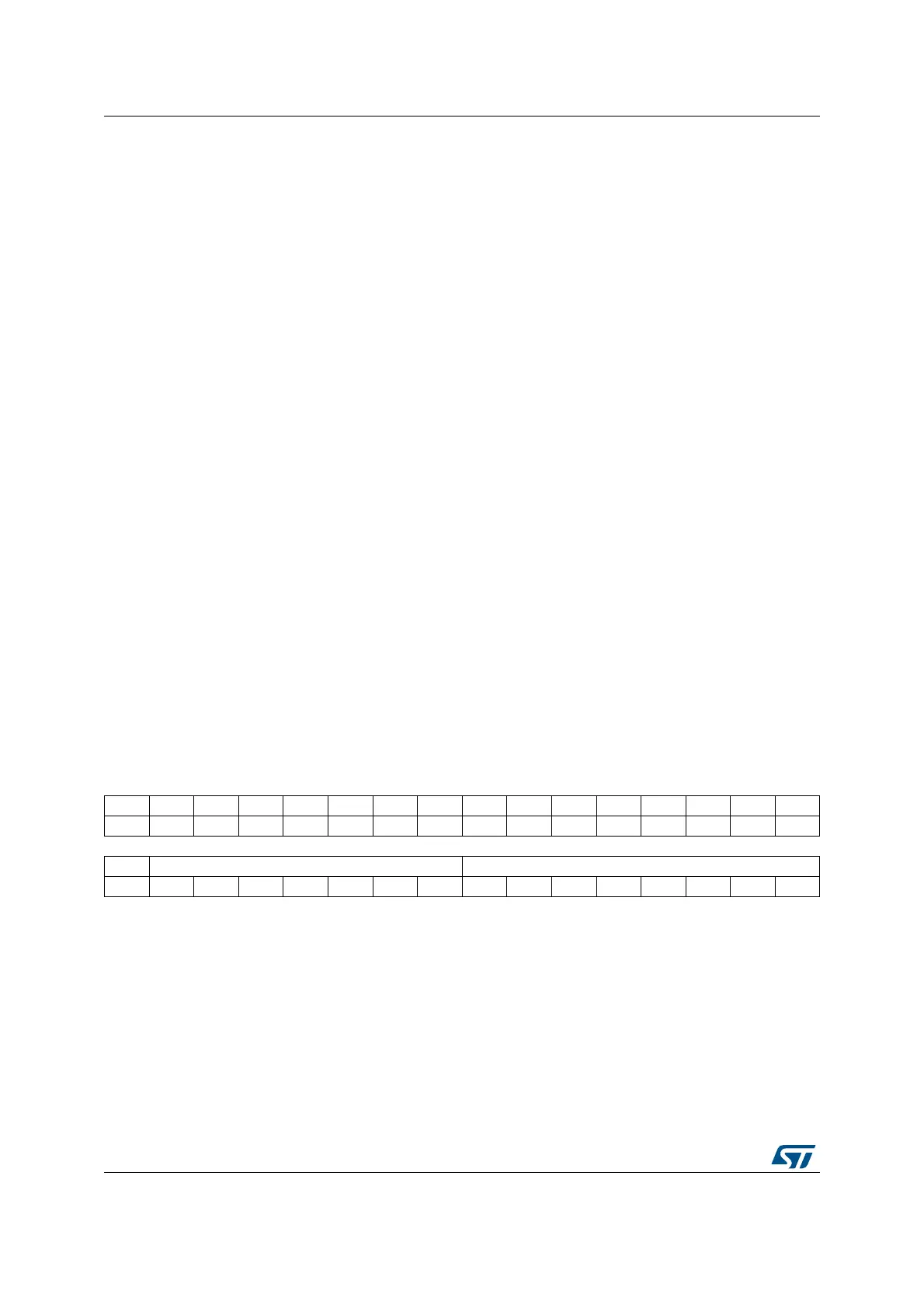
40.5.5 SAI frame configuration register (SAI_AFRCR)
Address offset: 0x00C
Reset value: 0x0000 0007
Note: This register has no meaning in AC’97 and SPDIF audio protocol.
Bit 4 TRIS: Tristate management on data line.
This bit is set and cleared by software. It is meaningful only if the audio block is configured as a
transmitter. This bit is not used when the audio block is configured in SPDIF mode. It should be
configured when SAI is disabled.
Refer to Section : Output data line management on an inactive slot for more details.
0: SD output line is still driven by the SAI when a slot is inactive.
1: SD output line is released (HI-Z) at the end of the last data bit of the last active slot if the next one
is inactive.
Bit 3 FFLUSH: FIFO flush.
This bit is set by software. It is always read as 0. This bit should be configured when the SAI is
disabled.
0: No FIFO flush.
1: FIFO flush. Programming this bit to 1 triggers the FIFO Flush. All the internal FIFO pointers (read
and write) are cleared. In this case data still present in the FIFO are lost (no more transmission or
received data lost). Before flushing, SAI DMA stream/interrupt must be disabled
Bits 2:0 FTH[2:0]: FIFO threshold.
This bit is set and cleared by software.
000: FIFO empty
001: ¼ FIFO
010: ½ FIFO
011: ¾ FIFO
100: FIFO full
101: Reserved
110: Reserved
111: Reserved
31 30 29 28 27 26 25 24 23 22 21 20 19 18 17 16
Res. Res. Res. Res. Res. Res. Res. Res. Res. Res. Res. Res. Res. FSOFF FSPOL FSDEF
rw rw r
1514131211109876543210
Res. FSALL[6:0] FRL[7:0]
rw rw rw rw rw rw rw rw rw rw rw rw rw rw rw
 Loading...


