RM0440 Rev 4 947/2126
RM0440 High-resolution timer (HRTIM)
1083
27.3.23 DMA
Most of the events able to generate an interrupt can also generate a DMA request, even
both simultaneously. Each timer (master, TIMA...F) has its own DMA enable register.
The individual DMA requests are ORed into 7 channels as follows:
• 1 channel for the master timer
• 1 channel per timing unit (TIMA...F)
Note: Before disabling a DMA channel (DMA enable bit reset in TIMxDIER), it is necessary to
disable first the DMA controller.
Table 240 is a summary of the events with their associated DMA enable bits.
hrtim_it2
hrtim_it3
hrtim_it4
hrtim_it5
hrtim_it6
hrtim_it7
Delayed protection triggered DLYPRT DLYPRTIE DLYPRTC
Counter reset or roll-over event RST RSTIE RSTC
Output 1 and output 2 reset (transition
active to inactive)
RSTx1 RSTx1IE RSTx1C
RSTx2 RSTx2IE RSTx2C
Output 1 and output 2 set (transition
inactive to active)
SETx1 SETx1IE SETx1C
SETx2 SETx2IE SETx2C
Capture 1 and 2 events
CPT1 CPT1IE CPT1C
CPT2 CPT2IE CPT2C
Timing unit registers update UPD UPDIE UPDC
Repetition event REP REPIE REPC
Compare 1 to 4 event
CMP1 CMP1IE CMP1C
CMP2 CMP2IE CMP2C
CMP3 CMP3IE CMP3C
CMP4 CMP4IE CMP4C
hrtim_it8
System fault SYSFLT SYSFLTIE SYSFLTC
Fault 1 to 6
FLT1 FLT1IE FLT1C
FLT2 FLT2IE FLT2C
FLT3 FLT3IE FLT3C
FLT4 FLT4IE FLT4C
FLT5 FLT5IE FLT5C
FLT6 FLT6IE FLT6C
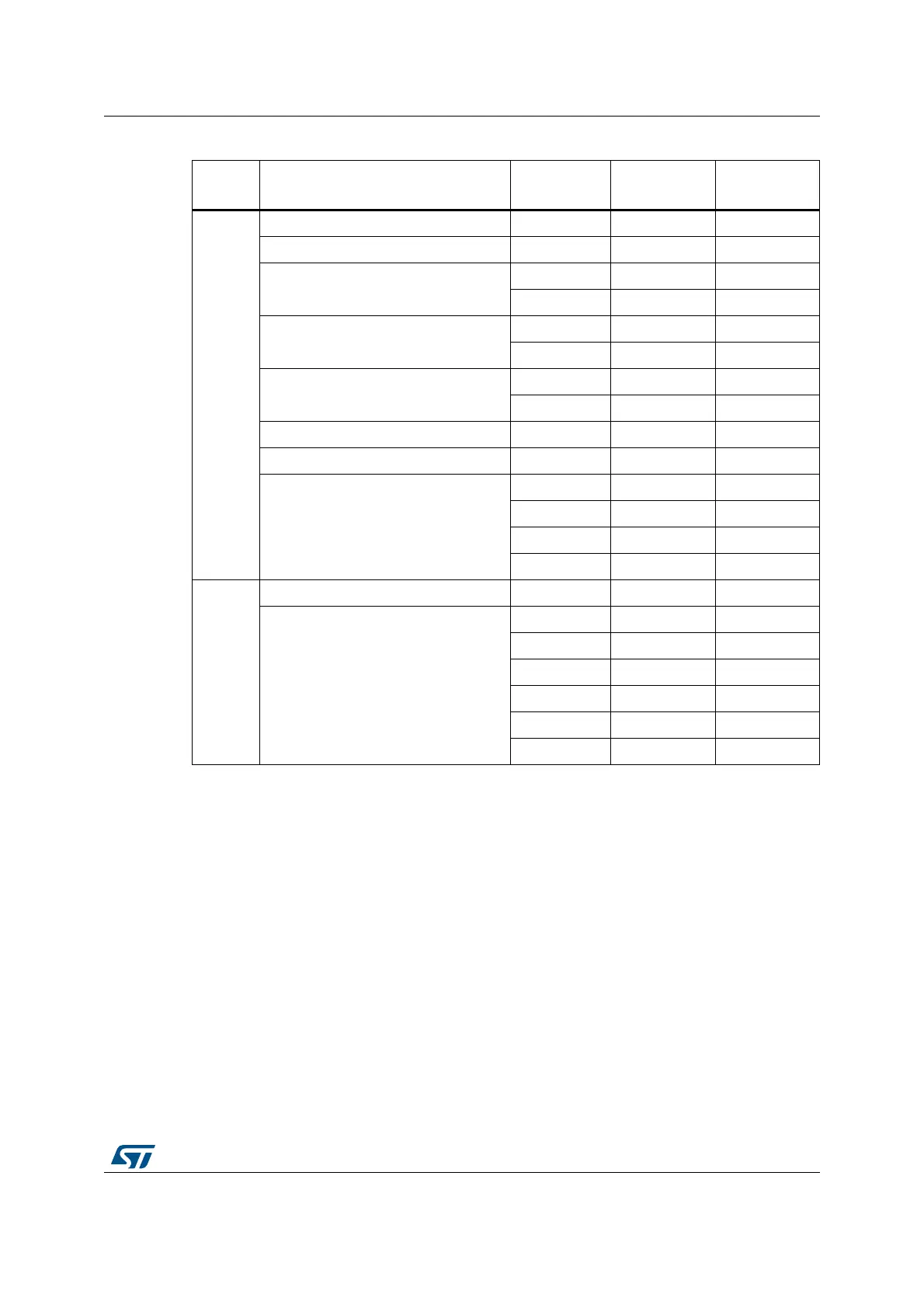
Table 239. HRTIM interrupt summary (continued)
Interrupt
vector
Interrupt event Event flag
Enable
control bit
Flag clearing
bit
 Loading...


