13 - 2
IPN 074-397-P1G
HAPSITE Smart Operating Manual
13.1.1 How the HSS Operates
The functions of the HSS are to provide consistent partition of analytes between
the sample and the headspace, and to transfer a representative sample of the
headspace to the HAPSITE for analysis.
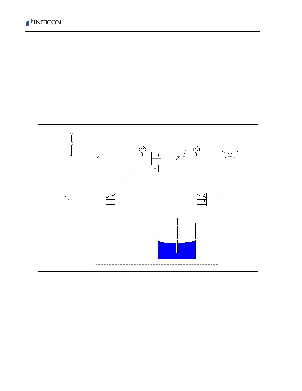
Figure 13-2 is a schematic of the gas flow system which accomplishes these
functions. The flow starts with the nitrogen supply, at the upper left. This can be
from disposable canisters or from an external cylinder supply. The nitrogen
pressure and flow are controlled by two pressure gauges, a shut-off valve, the
Variable Orifice valve and a fixed restrictor. All the valves in this system are
operated under software control.
Figure 13-2 HSS Operation Flow Diagram
Two three-way valves direct the flow to either bypass the vial (in the position
shown) or purge through the vial. While a sample is being transferred to the
HAPSITE, the flow is directed through the long needle, below the surface of the
sample. The nitrogen flow into the vial is approximately balanced by the
HAPSITE’s sample pump flow out of the vial. The headspace sample is transferred
to the HAPSITE while maintaining neutral pressure in the vial.
At the end of the analysis, if a Purge cycle is programmed, the operator is prompted
to insert the needles into a clean vial and acknowledge by pressing RUN. Purge is
achieved by providing a flow of clean nitrogen through the needles, heated line and
sample loop in the HAPSITE, removing residual organics and moisture from the
N2 Canister
External Supply
Carbon Filter
HAPSITE
Transfer
Line
Supply Pressure
Control Pressure
VSO Valve
VSO PCB
Fixed Restrictor
Headspace Oven