RM0440 Rev 4 1023/2126
RM0440 High-resolution timer (HRTIM)
1083
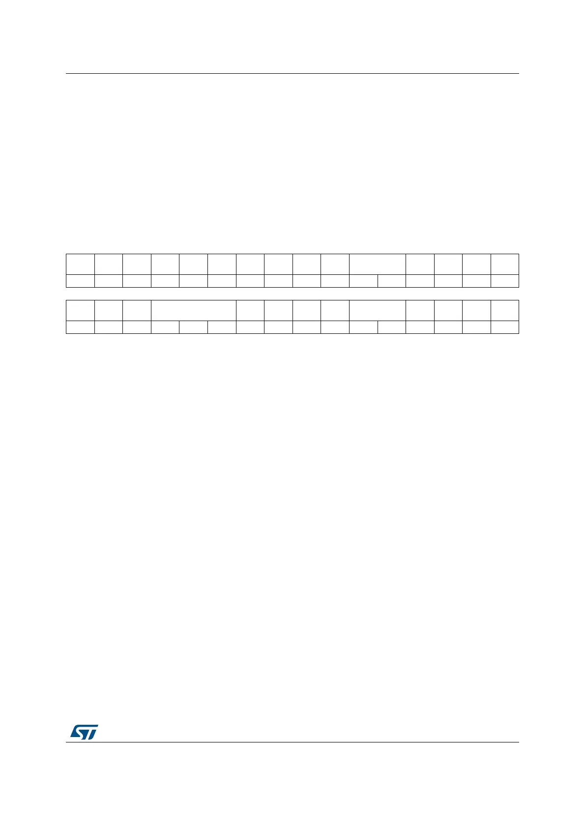
27.5.47 HRTIM timer x output register (HRTIM_OUTxR) (x = A to F)
Address offset: Block A: 0x0E4
Address offset: Block B: 0x164
Address offset: Block C: 0x1E4
Address offset: Block D: 0x264
Address offset: Block E: 0x2E4
Address offset: Block F: 0x364
Reset value: 0x0000 0000
31 30 29 28 27 26 25 24 23 22 21 20 19 18 17 16
Res. Res. Res. Res. Res. Res. Res. Res. DIDL2 CHP2 FAULT2[1:0 ] IDLES2
IDLEM
2
POL2 Res.
rw rw rw rw rw rw rw
1514131211109876543210
Res. BIAR Res. DLYPRT[2:0]
DLYPR
TEN
DTEN DIDL1 CHP1 FAULT1[1:0 ] IDLES1
IDLEM
1
POL1 Res.
rw rw rw rw rw rw rw rw rw rw rw rw rw
Bits 31:24 Reserved, must be kept at reset value.
Bit 23 DIDL2: Output 2 deadtime upon burst mode Idle entry
This bit delays the idle mode entry by forcing a deadtime insertion before switching the outputs to
their idle state. This setting only applies when entering in idle state during a burst mode operation.
0: The programmed Idle state is applied immediately to the output 2
1: Deadtime (inactive level) is inserted on output 2 before entering the idle mode. The deadtime
value is set by DTFx[8:0].
Note: This parameter cannot be changed once the timer x is enabled.
DIDL=1 is set only if one of the outputs is active during the burst mode (IDLES=1), and with
positive deadtimes (SDTR/SDTF set to 0).
Bit 22 CHP2: Output 2 chopper enable
This bit enables the chopper on output 2.
0: Output signal is not altered
1: Output signal is chopped by a carrier signal
Note: This parameter cannot be changed once the timer x is enabled.
Bits 21:20 FAULT2[1:0]: Output 2 fault state
These bits select the output 2 state after a fault event.
00: No action: the output is not affected by the fault input and stays in run mode.
01: Active
10: Inactive
11: High-Z
Note: This parameter cannot be changed once the timer x is enabled (TxCEN bit set), if FLTENx bit is
set or if the output is in FAULT state.
Bit 19 IDLES2: Output 2 idle state
This bit selects the output 2 idle state.
0: Inactive
1: Active
Note: This parameter must be set prior to have the HRTIM controlling the outputs.
 Loading...


