RM0440 Rev 4 1033/2126
RM0440 High-resolution timer (HRTIM)
1083
27.5.52 HRTIM control register 2 (HRTIM_CR2)
Address offset: 0x384
Reset value: 0x0000 0000
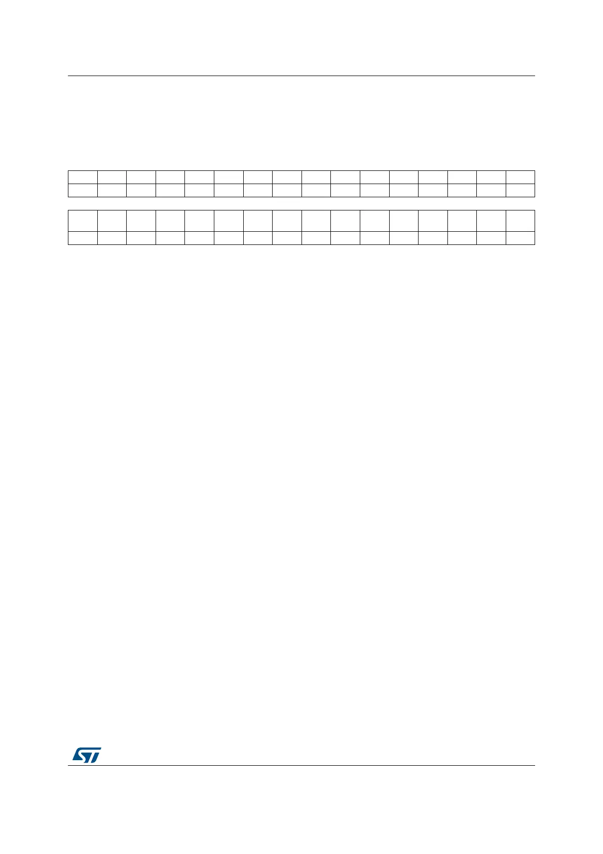
31 30 29 28 27 26 25 24 23 22 21 20 19 18 17 16
Res. Res. Res. Res. Res. Res. Res. Res. Res. Res. SWPF SWPE SWPD SWPC SWPB SWPA
rw rw rw rw rw rw
1514131211109876543210
Res. TFRST TERST TDRST TCRST TBRST TARST MRST Res.
TF
SWU
TE
SWU
TD
SWU
TC
SWU
TB
SWU
TA
SWU
MSWU
rw rw rw rw rw rw rw rw rw rw rw rw rw rw
Bits 31:22 Reserved, must be kept at reset value.
Bit 21 SWPF: Swap timer F outputs
Refer to SWPA description.
Note: This bit is not significant when the Push-pull mode is enabled (PSHPLL = 1).
Bit 20 SWPE: Swap timer E outputs
Refer to SWPA description.
Note: This bit is not significant when the Push-pull mode is enabled (PSHPLL = 1).
Bit 19 SWPD: Swap timer D outputs
Refer to SWPA description.
Note: This bit is not significant when the Push-pull mode is enabled (PSHPLL = 1).
Bit 18 SWPC: Swap timer C outputs
Refer to SWPA description.
Note: This bit is not significant when the Push-pull mode is enabled (PSHPLL = 1).
Bit 17 SWPB: Swap timer B outputs
Refer to SWPA description.
Note: This bit is not significant when the Push-pull mode is enabled (PSHPLL = 1).
Bit 16 SWPA: Swap timer A outputs
This bit allows to swap the timer A outputs.
0: HRTIM_SETA1R and HRTIM_RSTA1R are coding for the output A1, HRTIM_SETA2R and
HRTIM_RSTA2R are coding for the output A2
1: HRTIM_SETA1R and HRTIM_RSTA1R are coding for the output A2, HRTIM_SETA2R and
HRTIM_RSTA2R are coding for the output A1
Note: This bit is not significant when the Push-pull mode is enabled (PSHPLL = 1).
Bit 15 Reserved, must be kept at reset value.
Bit 14 TFRST: Timer F counter software reset
Refer to TARST description.
Bit 13 TERST: Timer E counter software reset
Refer to TARST description.
Bit 12 TDRST: Timer D counter software reset
Refer to TARST description.
Bit 11 TCRST: Timer C counter software reset
Refer to TARST description.
 Loading...


