RM0440 Rev 4 1059/2126
RM0440 High-resolution timer (HRTIM)
1083
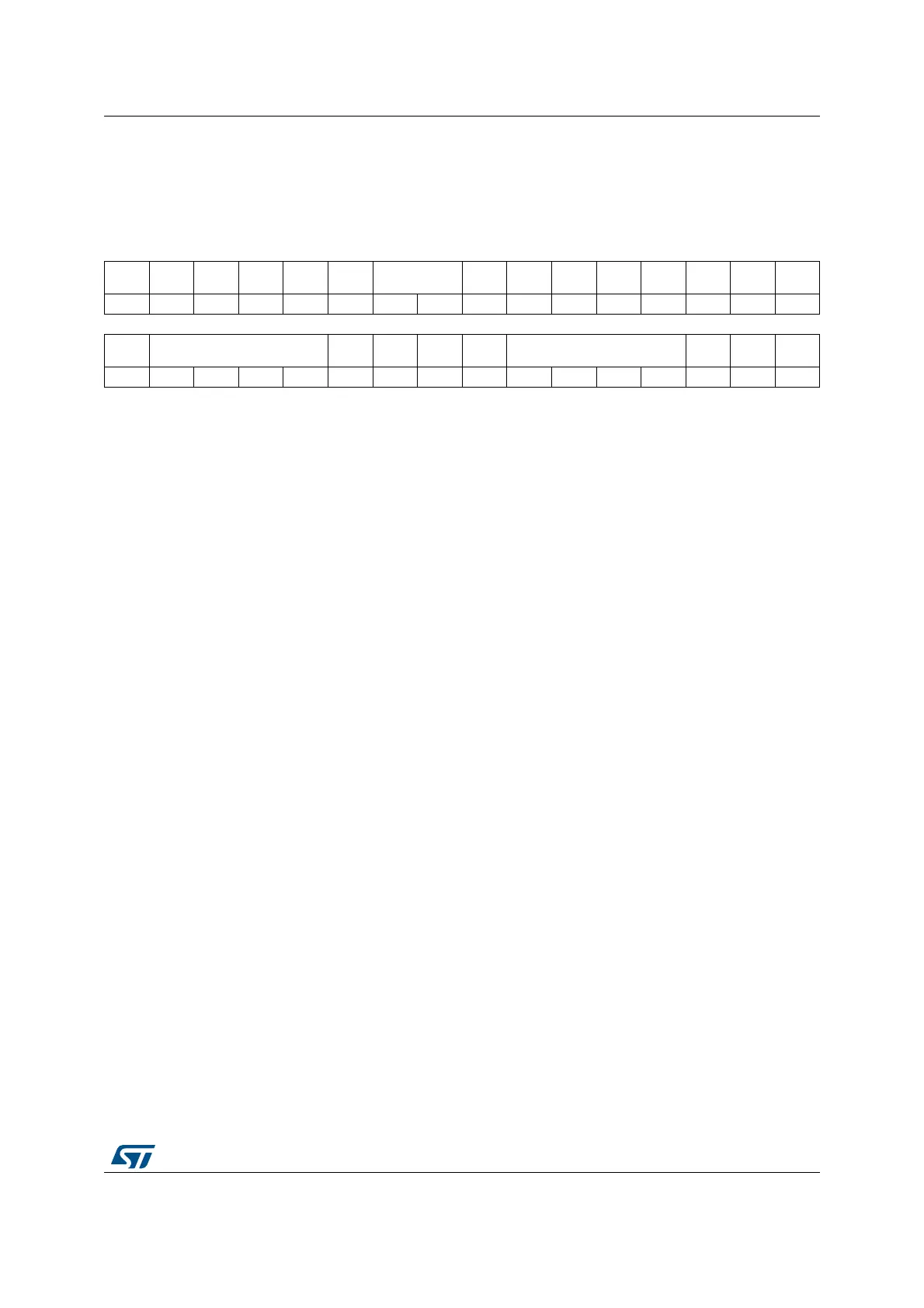
27.5.72 HRTIM fault input register 2 (HRTIM_FLTINR2)
Address offset: 0x3D4
Reset value: 0x0000 0000
31 30 29 28 27 26 25 24 23 22 21 20 19 18 17 16
Res. Res. Res. Res. Res. Res. FLTSD[1:0] Res. Res.
FLT6
SRC[1]
FLT5
SRC[1]
FLT4
SRC[1]
FLT3
SRC[1]
FLT2
SRC[1]
FLT1
SRC[1]
rw rw rw rw rw rw rw rw
1514131211109876543210
FLT6
LCK
FLT6F[3:0]
FLT6
SRC[0]
FLT6P FLT6E
FLT5
LCK
FLT5F[3:0]
FLT5
SRC[0]
FLT5P FLT5E
rwo rw rw rw rw rw rw rw rwo rw rw rw rw rw rw rw
Bits 31:26 Reserved, must be kept at reset value.
Bits 25:24 FLTSD[1:0]: Fault sampling clock division
This bitfield indicates the division ratio between the timer clock frequency (f
HRTIM
) and the fault
signal sampling clock (f
FLTS
) used by the digital filters.
00: f
FLTS
=f
HRTIM
01: f
FLTS
=f
HRTIM
/ 2
10: f
FLTS
=f
HRTIM
/ 4
11: f
FLTS
=f
HRTIM
/ 8
Note: This bitfield must be written prior to any of the FLTxE enable bits.
Bits 23:21 Reserved, must be kept at reset value.
Bit 21 FLT6SRC[1]: Fault 6 source bit 1
Refer to FLT5SRC[0] description.
Bit 20 FLT5SRC[1]: Fault 5 source bit 1
Refer to FLT5SRC[0] description.
Bit 19 FLT4SRC[1]: Fault 4 source bit 1
Refer to FLT5SRC[0] description.
Bit 18 FLT3SRC[1]: Fault 3 source bit 1
Refer to FLT5SRC[0] description.
Bit 17 FLT2SRC[1]: Fault 2 source bit 1
Refer to FLT5SRC[0] description.
Bit 16 FLT1SRC[1]: Fault 1 source bit 1
Refer to FLT5SRC[0] description.
Bit 15 FLT6LCK: Fault 6 lock
Refer to FLT5LCK description.
Bits 14:11 FLT6F[3:0]: Fault 6 filter
Refer to FLT5F[3:0] description.
Bit 10 FLT6SRC[0]: Fault 6 source bit 0
Refer to FLT5SRC[0] description.
Bit 9 FLT6P: Fault 6 polarity
Refer to FLT5P description.
 Loading...


