RM0440 Rev 4 1125/2126
RM0440 Advanced-control timers (TIM1/TIM8/TIM20)
1226
28.3.14 Asymmetric PWM mode
Asymmetric mode allows two center-aligned PWM signals to be generated with a
programmable phase shift. While the frequency is determined by the value of the
TIMx_ARR register, the duty cycle and the phase-shift are determined by a pair of
TIMx_CCRx register. One register controls the PWM during up-counting, the second during
down counting, so that PWM is adjusted every half PWM cycle:
– tim_oc1refc (or tim_oc2refc) is controlled by TIMx_CCR1 and TIMx_CCR2
– tim_oc3refc (or tim_oc4refc) is controlled by TIMx_CCR3 and TIMx_CCR4
Asymmetric PWM mode can be selected independently on two channel (one tim_ocx output
per pair of CCR registers) by writing ‘1110’ (Asymmetric PWM mode 1) or ‘1111’
(Asymmetric PWM mode 2) in the OCxM bits in the TIMx_CCMRx register.
Note: The OCxM[3:0] bit field is split into two parts for compatibility reasons, the most significant
bit is not contiguous with the 3 least significant ones.
When a given channel is used as asymmetric PWM channel, its complementary channel
can also be used. For instance, if an tim_oc1refc signal is generated on channel 1
(Asymmetric PWM mode 1), it is possible to output either the tim_oc2ref signal on channel
2, or an tim_oc2refc signal resulting from asymmetric PWM mode 1.
Figure 309 represents an example of signals that can be generated using Asymmetric PWM
mode (channels 1 to 4 are configured in Asymmetric PWM mode 2). Together with the
deadtime generator, this allows a full-bridge phase-shifted DC to DC converter to be
controlled.
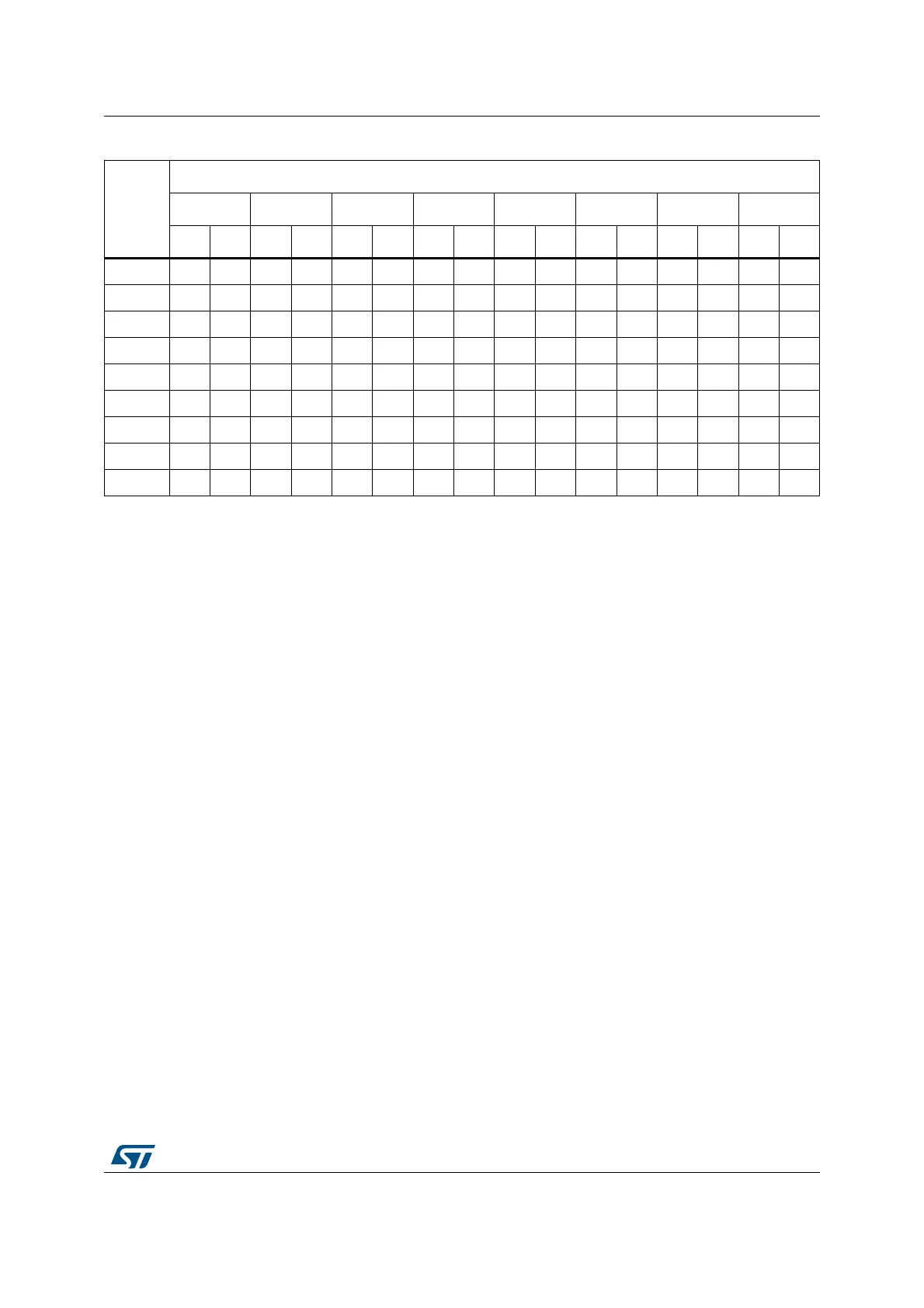
0111 +1 - +1 - +1 - +1 - +1 - +1 - +1 - - -
1000 +1-+1-+1-+1-+1-+1-+1-+1-
1001 +1 +1 +1 - +1 - +1 - +1 - +1 - +1 - +1 -
1010 +1 +1 +1 - +1 - +1 - +1 +1 +1 - +1 - +1 -
1011 +1 +1 +1 - +1 +1 +1 - +1 +1 +1 - +1 - +1 -
1100 +1 +1 +1 - +1 +1 +1 - +1 +1 +1 - +1 +1 +1 -
1101 +1 +1 +1 +1 +1 +1 +1 - +1 +1 +1 - +1 +1 +1 -
1110 +1 +1 +1 +1 +1 +1 +1 - +1 +1 +1 +1 +1 +1 +1 -
1111 +1 +1 +1 +1 +1 +1 +1 +1 +1 +1 +1 +1 +1 +1 +1 -
Table 257. CCR register change dithering pattern in center-aligned PWM mode (continued)
LSB
value
PWM period
12345678
Up DnUpDnUpDnUpDnUpDnUpDnUpDnUpDn

 Loading...