Analog-to-digital converters (ADC) RM0440
704/2126 RM0440 Rev 4
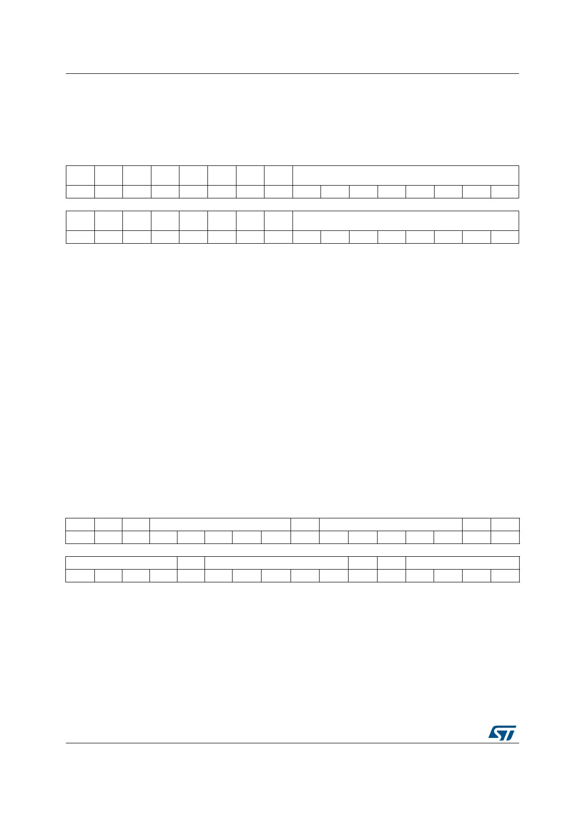
21.6.10 ADC watchdog threshold register 3 (ADC_TR3)
Address offset: 0x28
Reset value: 0x00FF 0000
21.6.11 ADC regular sequence register 1 (ADC_SQR1)
Address offset: 0x30
Reset value: 0x0000 0000
31 30 29 28 27 26 25 24 23 22 21 20 19 18 17 16
Res. Res. Res. Res. Res. Res. Res. Res. HT3[7:0]
rw rw rw rw rw rw rw rw
1514131211109876543210
Res. Res. Res. Res. Res. Res. Res. Res. LT3[7:0]
rw rw rw rw rw rw rw rw
Bits 31:24 Reserved, must be kept at reset value.
Bits 23:16 HT3[7:0]: Analog watchdog 3 higher threshold
These bits are written by software to define the higher threshold for the analog watchdog 3.
Refer to Section 21.4.28: Analog window watchdog (AWD1EN, JAWD1EN, AWD1SGL, AWD1CH,
AWD2CH, AWD3CH, AWD_HTx, AWD_LTx, AWDx)
Note: The software is allowed to write these bits only when ADSTART=0 and JADSTART=0 (which
ensures that no conversion is ongoing).
Bits 15:8 Reserved, must be kept at reset value.
Bits 7:0 LT3[7:0]: Analog watchdog 3 lower threshold
These bits are written by software to define the lower threshold for the analog watchdog 3.
This watchdog compares the 8-bit of LT3 with the 8 MSB of the converted data.
Note: The software is allowed to write these bits only when ADSTART=0 and JADSTART=0 (which
ensures that no conversion is ongoing).
31 30 29 28 27 26 25 24 23 22 21 20 19 18 17 16
Res. Res. Res. SQ4[4:0] Res. SQ3[4:0] Res. SQ2[4]
rw rw rw rw rw rw rw rw rw rw rw
15 14 13 12 11 10 9 8 7 6 5 4 3 2 1 0
SQ2[3:0] Res. SQ1[4:0] Res. Res. L[3:0]
rw rw rw rw rw rw rw rw rw rw rw rw rw
Bits 31:29 Reserved, must be kept at reset value.
Bits 28:24 SQ4[4:0]: 4th conversion in regular sequence
These bits are written by software with the channel number (0 to 18) assigned as the 4th in
the regular conversion sequence.
Note: The software is allowed to write these bits only when ADSTART=0 (which ensures that
no regular conversion is ongoing).
Bit 23 Reserved, must be kept at reset value.
 Loading...


