Analog-to-digital converters (ADC) RM0440
712/2126 RM0440 Rev 4
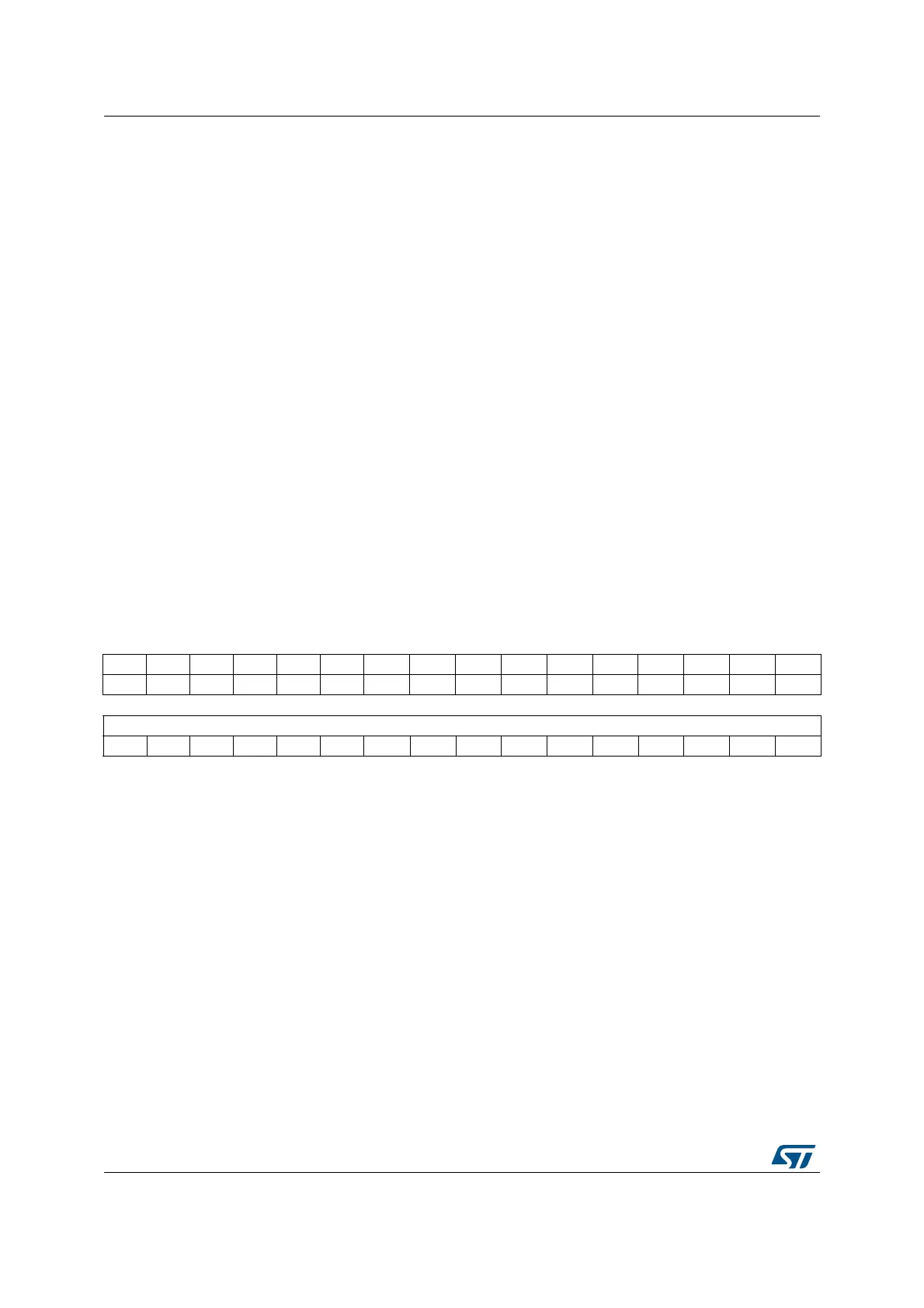
21.6.18 ADC injected channel y data register (ADC_JDRy)
Address offset: 0x80 + 0x04 * (y - 1), (y = 1 to 4)
Reset value: 0x0000 0000
Bit 24 OFFSETPOS: Positive offset
This bit is set and cleared by software to enable the positive offset.
0: Negative offset
1: Positive offset
Note: The software is allowed to write these bits only when ADSTART=0 and JADSTART=0
(which ensures that no conversion is ongoing).
Bits 23:12 Reserved, must be kept at reset value.
Bits 11:0 OFFSETy[11:0]: Data offset y for the channel programmed into bits OFFSETy_CH[4:0]
These bits are written by software to define the offset y to be subtracted from the raw
converted data when converting a channel (can be regular or injected). The channel to which
applies the data offset y must be programmed in the bits OFFSETy_CH[4:0]. The conversion
result can be read from in the ADC_DR (regular conversion) or from in the ADC_JDRyi
registers (injected conversion).
Note: The software is allowed to write these bits only when ADSTART=0 and JADSTART=0
(which ensures that no conversion is ongoing).
If several offset (OFFSETy) point to the same channel, only the offset with the lowest x
value is considered for the subtraction.
Ex: if OFFSET1_CH[4:0]=4 and OFFSET2_CH[4:0]=4, this is OFFSET1[11:0] which is
subtracted when converting channel 4.
31 30 29 28 27 26 25 24 23 22 21 20 19 18 17 16
Res. Res. Res. Res. Res. Res. Res. Res. Res. Res. Res. Res. Res. Res. Res. Res.
1514131211109876543210
JDATA[15:0]
rrrrrr r r r r rrrrrr
Bits 31:16 Reserved, must be kept at reset value.
Bits 15:0 JDATA[15:0]: Injected data
These bits are read-only. They contain the conversion result from injected channel y. The
data are left -or right-aligned as described in Section 21.4.26: Data management.
 Loading...


