Analog-to-digital converters (ADC) RM0440
714/2126 RM0440 Rev 4
21.6.21 ADC differential mode selection register (ADC_DIFSEL)
Address offset: 0xB0
Reset value: 0x0000 0000
Bits 31:19 Reserved, must be kept at reset value.
Bits 18:0 AWD3CH[18:0]: Analog watchdog 3 channel selection
These bits are set and cleared by software. They enable and select the input channels to be guarded
by the analog watchdog 3.
AWD3CH[i] = 0: ADC analog input channel i is not monitored by AWD3
AWD3CH[i] = 1: ADC analog input channel i is monitored by AWD3
When AWD3CH[18:0] = 000..0, the analog watchdog 3 is disabled
Note: The channels selected by AWD3CH must be also selected into the SQRi or JSQRi registers.
The software is allowed to write these bits only when ADSTART=0 and JADSTART=0 (which
ensures that no conversion is ongoing).
Some channels are not connected physically and must not be selected for the analog
watchdog.
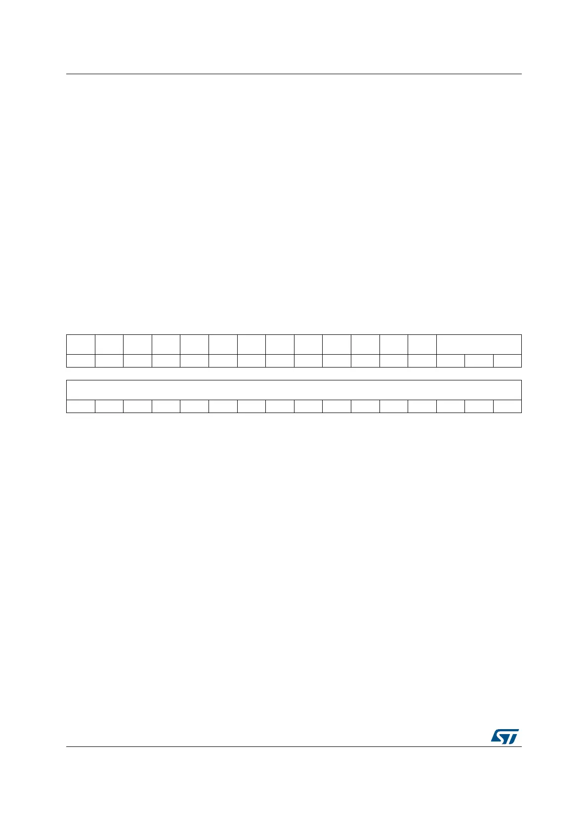
31 30 29 28 27 26 25 24 23 22 21 20 19 18 17 16
Res. Res. Res. Res. Res. Res. Res. Res. Res. Res. Res. Res. Res. DIFSEL[18:16]
rw rw rw
1514131211109876543210
DIFSEL[15:0]
rw rw rw rw rw rw rw rw rw rw rw rw rw rw rw r
Bits 31:19 Reserved, must be kept at reset value.
Bits 18:0 DIFSEL[18:0]: Differential mode for channels 18 to 0.
These bits are set and cleared by software. They allow to select if a channel is configured as single-
ended or differential mode.
DIFSEL[i] = 0: ADC analog input channel is configured in single ended mode
DIFSEL[i] = 1: ADC analog input channel i is configured in differential mode
Note: The DIFSEL bits corresponding to channels that are either connected to a single-ended I/O port
or to an internal channel must be kept their reset value (single-ended input mode).
The software is allowed to write these bits only when the ADC is disabled (ADCAL=0,
JADSTART=0, JADSTP=0, ADSTART=0, ADSTP=0, ADDIS=0 and ADEN=0).
 Loading...


