RM0440 Rev 4 763/2126
RM0440 Digital-to-analog converter (DAC)
773
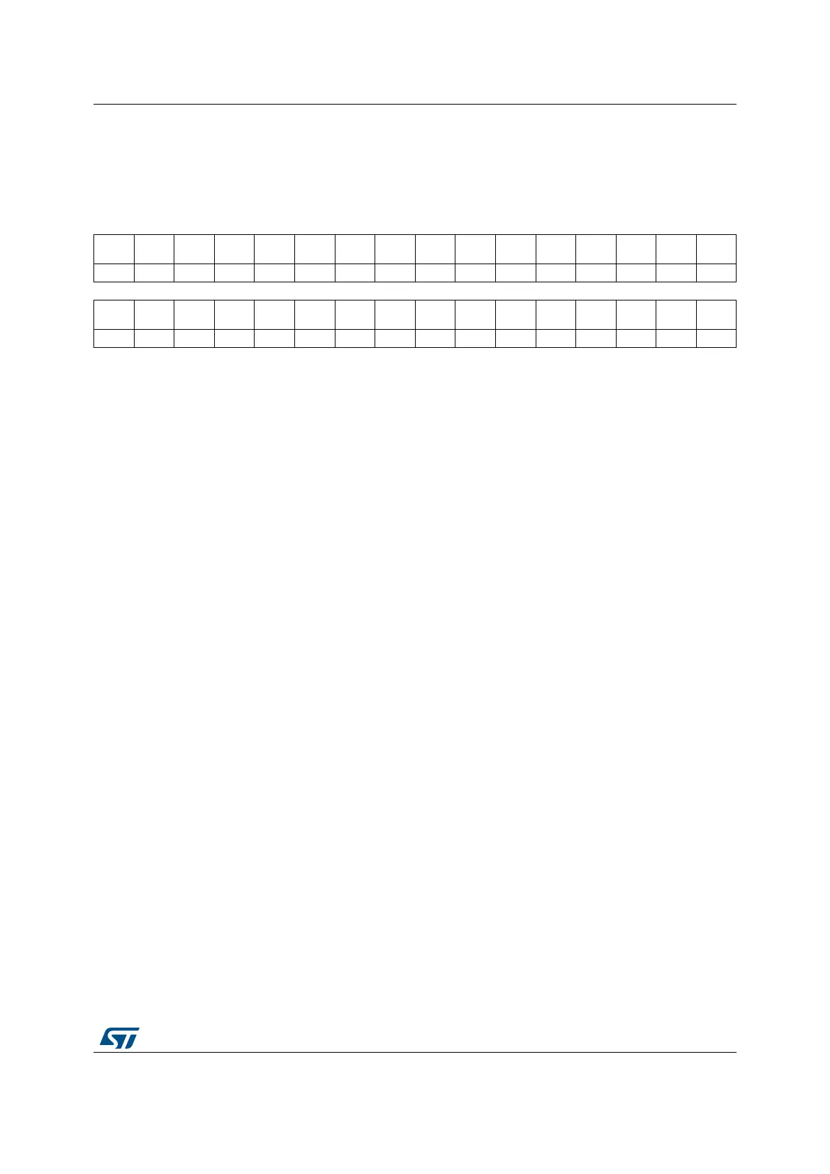
22.7.14 DAC status register (DAC_SR)
Address offset: 0x34
Reset value: 0x0000 0000
31 30 29 28 27 26 25 24 23 22 21 20 19 18 17 16
BWST2
CAL_
FLAG2
DMAU
DR2
DORST
AT2
DAC2R
DY
Res. Res. Res. Res. Res. Res. Res. Res. Res. Res. Res.
rrrc_w1rr
1514131211109876543210
BWST1
CAL_
FLAG1
DMAU
DR1
DORST
AT1
DAC1R
DY
Res. Res. Res. Res. Res. Res. Res. Res. Res. Res. Res.
rrrc_w1rr
Bit 31 BWST2: DAC channel2 busy writing sample time flag
This bit is systematically set just after Sample and hold mode enable. It is set each time the
software writes the register DAC_SHSR2, It is cleared by hardware when the write operation
of DAC_SHSR2 is complete. (It takes about 3 LSI/LSE periods of synchronization).
0:There is no write operation of DAC_SHSR2 ongoing: DAC_SHSR2 can be written
1:There is a write operation of DAC_SHSR2 ongoing: DAC_SHSR2 cannot be written
Note: This bit is available only on dual-channel DACs. Refer to Section 22.3: DAC
implementation.
Bit 30 CAL_FLAG2: DAC channel2 calibration offset status
This bit is set and cleared by hardware
0: calibration trimming value is lower than the offset correction value
1: calibration trimming value is equal or greater than the offset correction value
Note: This bit is available only on dual-channel DACs. Refer to Section 22.3: DAC
implementation.
Bit 29 DMAUDR2: DAC channel2 DMA underrun flag
This bit is set by hardware and cleared by software (by writing it to 1).
0: No DMA underrun error condition occurred for DAC channel2
1: DMA underrun error condition occurred for DAC channel2 (the currently selected trigger is
driving DAC channel2 conversion at a frequency higher than the DMA service capability
rate).
Note: This bit is available only on dual-channel DACs. Refer to Section 22.3: DAC
implementation.
Bit 28 DORSTAT2: DAC channel2 output register status bit
This bit is set and cleared by hardware. It is applicable only when the DAC operates in
Double data mode.
0: DOR[11:0] is used actual DAC output
1: DORB[11:0] is used actual DAC output
Note: This bit is available only on dual-channel DACs. Refer to Section 22.3: DAC
implementation.
Bit 27 DAC2RDY: DAC channel2 ready status bit
This bit is set and cleared by hardware.
0: DAC channel2 is not yet ready to accept the trigger nor output data
1: DAC channel2 is ready to accept the trigger or output data
Note: This bit is available only on dual-channel DACs. Refer to Section 22.3: DAC
implementation.
 Loading...


