RM0440 Rev 4 765/2126
RM0440 Digital-to-analog converter (DAC)
773
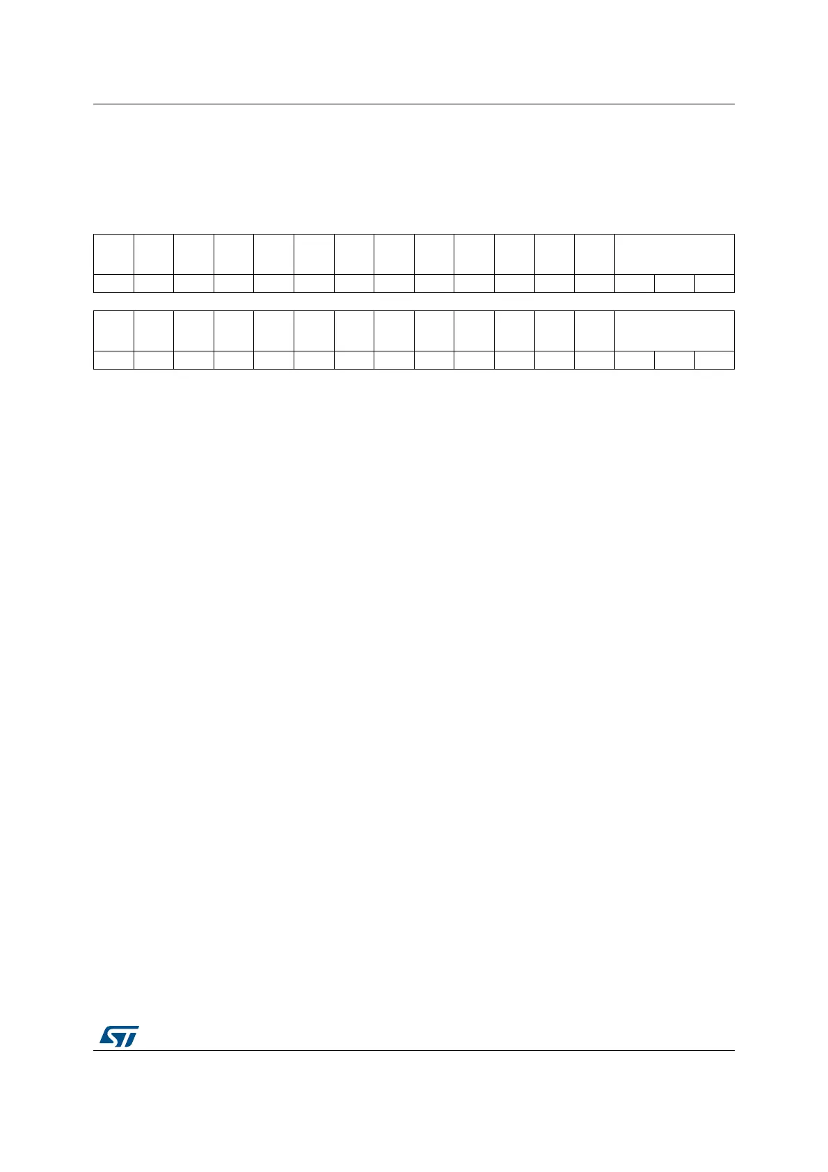
22.7.16 DAC mode control register (DAC_MCR)
Address offset: 0x3C
Reset value: 0x0000 0000
31 30 29 28 27 26 25 24 23 22 21 20 19 18 17 16
Res. Res. Res. Res. Res. Res.
SINFO
RMAT2
DMAD
OUBLE
2
Res. Res. Res. Res. Res. MODE2[2:0]
rw rw rw rw rw
1514131211109876543210
HFSEL
1
HFSEL
0
Res. Res. Res. Res.
SINFO
RMAT1
DMAD
OUBLE
1
Res. Res. Res. Res. Res. MODE1[2:0]
rw rw rw rw rw rw rw
Bits 31:26 Reserved, must be kept at reset value.
Bit 25 SINFORMAT2: Enable signed format for DAC channel2
This bit is set and cleared by software.
0: Input data is in unsigned format
1: Input data is in signed format (2’s complement). The MSB bit represents the sign.
Note: This bit is available only on dual-channel DACs. Refer to Section 22.3: DAC
implementation.
Bit 24 DMADOUBLE2: DAC channel2 DMA double data mode
This bit is set and cleared by software.
0: DMA Normal mode selected
1: DMA Double data mode selected
Note: This bit is available only on dual-channel DACs. Refer to Section 22.3: DAC
implementation.
Bits 23:19 Reserved, must be kept at reset value.
Bits 18:16 MODE2[2:0]: DAC channel2 mode
These bits can be written only when the DAC is disabled and not in the calibration mode
(when bit EN2=0 and bit CEN2 =0 in the DAC_CR register). If EN2=1 or CEN2 =1 the write
operation is ignored.
They can be set and cleared by software to select the DAC channel2 mode:
– DAC channel2 in Normal mode
000: DAC channel2 is connected to external pin with Buffer enabled
001: DAC channel2 is connected to external pin and to on chip peripherals with buffer
enabled
010: DAC channel2 is connected to external pin with buffer disabled
011: DAC channel2 is connected to on chip peripherals with Buffer disabled
– DAC channel2 in Sample and hold mode
100: DAC channel2 is connected to external pin with Buffer enabled
101: DAC channel2 is connected to external pin and to on chip peripherals with Buffer
enabled
110: DAC channel2 is connected to external pin and to on chip peripherals with Buffer
disabled
111: DAC channel2 is connected to on chip peripherals with Buffer disabled
Note: This register can be modified only when EN2=0.
Refer to Section 22.3: DAC implementation for the availability of DAC channel2.
 Loading...


