RM0440 Rev 4 975/2126
RM0440 High-resolution timer (HRTIM)
1083
27.5.13 HRTIM timer x interrupt status register (HRTIM_TIMxISR)
(x = A to F)
Address offset: Block A: 0x084
Address offset: Block B: 0x104
Address offset: Block C: 0x184
Address offset: Block D: 0x204
Address offset: Block E: 0x284
Address offset: Block F: 0x304
Reset value: 0x000 0000
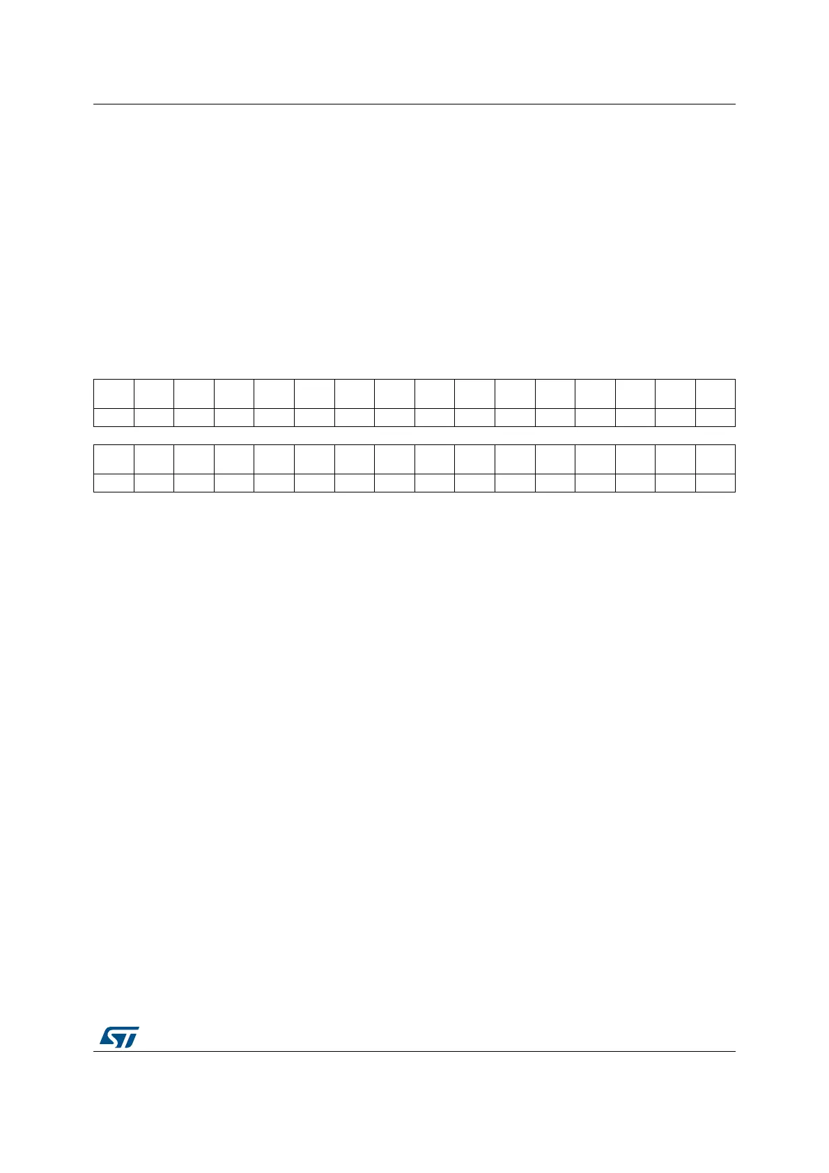
31 30 29 28 27 26 25 24 23 22 21 20 19 18 17 16
Res. Res. Res. Res. Res. Res. Res. Res. Res. Res. O2CPY O1CPY
O2
STAT
O1
STAT
IPP
STAT
CPP
STAT
rrrrrr
1514131211109876543210
Res.
DLYPR
T
RST RSTx2 SETx2 RSTx1 SETx1 CPT2 CPT1 UPD Res. REP CMP4 CMP3 CMP2 CMP1
rrrrrrrrr rrrrr
Bits 31:22 Reserved, must be kept at reset value.
Bit 21 O2CPY: Output 2 copy
This status bit is a raw copy of the output 2 state, before the output stage (chopper, polarity). It allows
to check the current output state before re-enabling the output after a delayed protection.
0: Output 2 is inactive
1: Output 2 is active
Bit 20 O1CPY: Output 1 copy
This status bit is a raw copy of the output 1 state, before the output stage (chopper, polarity). It allows
to check the current output state before re-enabling the output after a delayed protection.
0: Output 1 is inactive
1: Output 1 is active
Bit 19 O2STAT: Output 2 status
This status bit indicates the output 2 state when the delayed idle protection was triggered. This bit is
updated upon any new delayed protection entry. This bit is not updated in balanced idle.
0: Output 2 was inactive
1: Output 2 was active
Bit 18 O1STAT: Output 1 status
This status bit indicates the output 1 state when the delayed idle protection was triggered. This bit is
updated upon any new delayed protection entry. This bit is not updated in balanced idle.
0: Output 1 was inactive
1: Output 1 was active
Bit 17 IPPSTAT: Idle push-pull Status
This status bit indicates on which output the signal was applied, in push-pull mode balanced fault
mode or delayed idle mode, when the protection was triggered (whatever the output state, active or
inactive).
0: Protection occurred when the output 1 was active and output 2 forced inactive
1: Protection occurred when the output 2 was active and output 1 forced inactive
 Loading...


