Chapter 2 Hardware Connections
Management Switch Card User’s Guide
58
To signal a major alarm, the MSC opens the circuit for pins 13 and 6 and closes the circuit for pins
14 and 6.
To signal a critical alarm, the MSC opens the circuit for pins 7 and 15 and closes the circuit for pins
8 and 15.
Examples of an alarm on the MSC are when the MSC’s voltage or temperature is outside of the
normal range.
2.3.2 Gigabit and 10 Gigabit Ethernet Interfaces
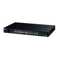
MSC1000G
• Interfaces 1 and 2 are Gigabit Ethernet SFP slots.
• Interfaces 3 and 4 are Gigabit Ethernet port/SFP slot pairs.
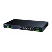
MSC1024G
• Interfaces 1 through 4 are Gigabit Ethernet SFP slots.
• Interfaces 5 and 6 are Gigabit Ethernet port/SFP slot pairs.
• Interfaces 7 and 8 are Gigabit Ethernet ports.
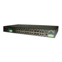
MSC1224G
• Interfaces 1 and 2 are 10 Gigabit Ethernet XFP slots.
• Interfaces 3 and 4 are Gigabit Ethernet SFP slots.
• Interfaces 5 and 6 are Gigabit Ethernet port/SFP slot pairs.
• Interfaces 7 and 8 are Gigabit Ethernet ports.
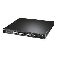
MSC1024GB/MSC1024GC
• Interfaces 1 through 4 are Gigabit Ethernet port/SFP slot pairs.
MSC1224GB
• Interfaces SFP+ 1 and SFP+ 2 are 10 Gigabit Ethernet SFP+ slots.
• Interfaces 1 through 4 are Gigabit Ethernet port/SFP slot pairs.
The SFP slots have priority over the Gigabit ports. This means that if a SFP transceiver and the
corresponding Gigabit port are connected at the same time, the Gigabit port will be disabled.
To avoid possible eye injury, do not look into an operating fiber-optic
module’s connectors.
The Ethernet ports are auto-negotiating and can detect and adjust to the optimum Ethernet speed
(100/1000 Mbps) and duplex mode (full duplex or half duplex) of the connected device. The
Ethernet ports are also auto-crossover (auto-MDI/MDI-X), they automatically work with a straight-
through or crossover Ethernet cable.
 Loading...