5-36 Bus Interface
AMD-K5 Processor Technical Reference Manual 18524C/0—Nov1996
5.2.9 BF (Bus Frequency)—(BF1–BF0 for Model 1)
Input
Summary During RESET, BF (BF1–BF0) selects between a high and low
multiplication factor for the frequency ratio between the pro-
cessor’s internal clock and the bus clock (CLK).
Sampled The processor samples BF (BF1–BF0) only on the falling edge
of RESET. The signal assertion must be stable 10 clocks prior
to its sampling. BF (BF1–BF0) has a weak internal pullup resis-
tor; see the data sheet for details.
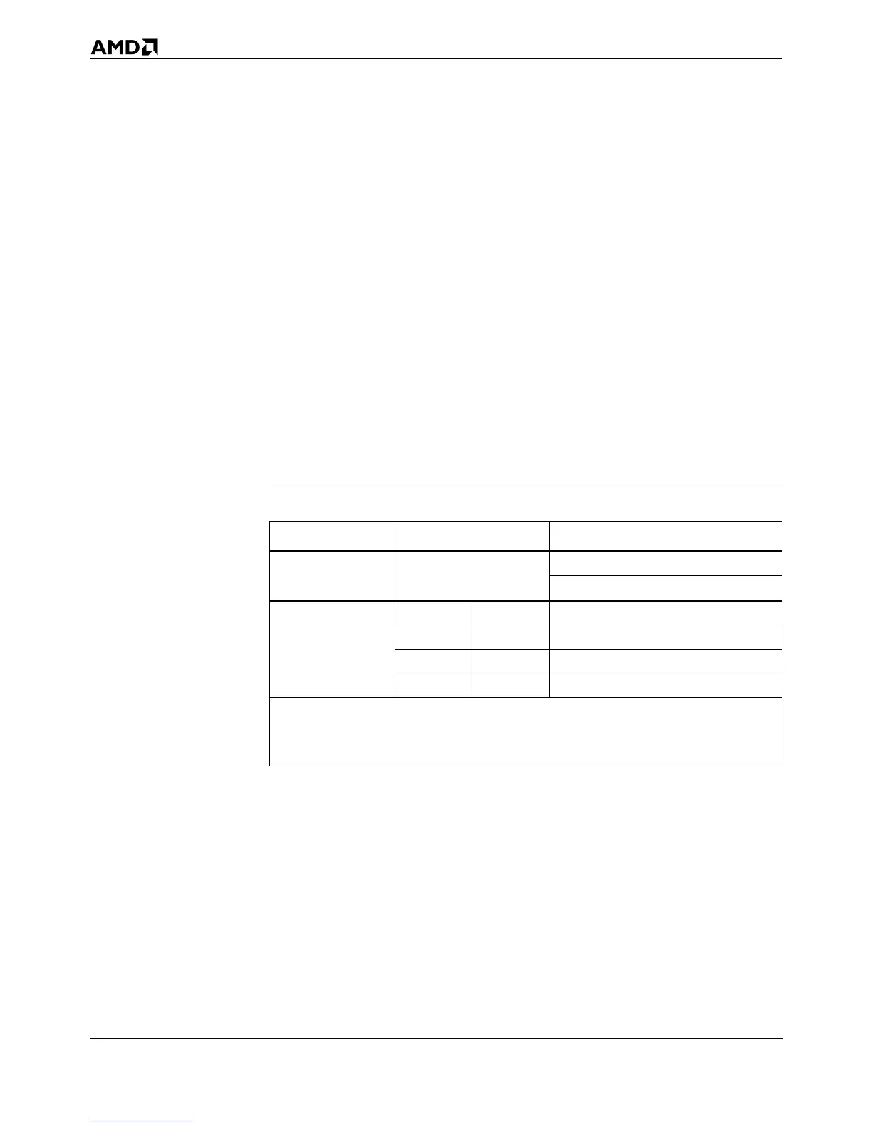
Details Table 5-7 shows the ratios between the processor clock and the
bus clock (CLK) for the High and Low values of BF (BF1–BF0).
BF (BF1–BF0) may be tied High or Low. Due to the internal
pullup resistor, the lower ratio is selected if BF (BF1–BF0) is
left unconnected.
Table 5-7. Processor-to-Bus Clock Ratios
Processor Model State of BF Input(s) Processor-Clock to Bus-Clock Ratio
0
BF = 1
BF = 0
1.5x
2.0x
1
BF1 = 1 BF0 = 1 1.5x
BF1 = 1 BF0 = 0 1.5x
BF1 = 0 BF0 = 1 Reserved
BF1 = 0 BF0 = 0 Reserved
Notes:
1. The default processor-to-clock ratios are shown in Table 5-7. Specific models of the AMD-K5
processor may implement different ratios for the High and Low values of BF. For authorative
information, see the data sheet for each AMD-K5 processor model.