Signal Overview 5-7
18524C/0—Nov1996 AMD-K5 Processor Technical Reference Manual
5.1.2 Conditions for Driving and Sampling Signals
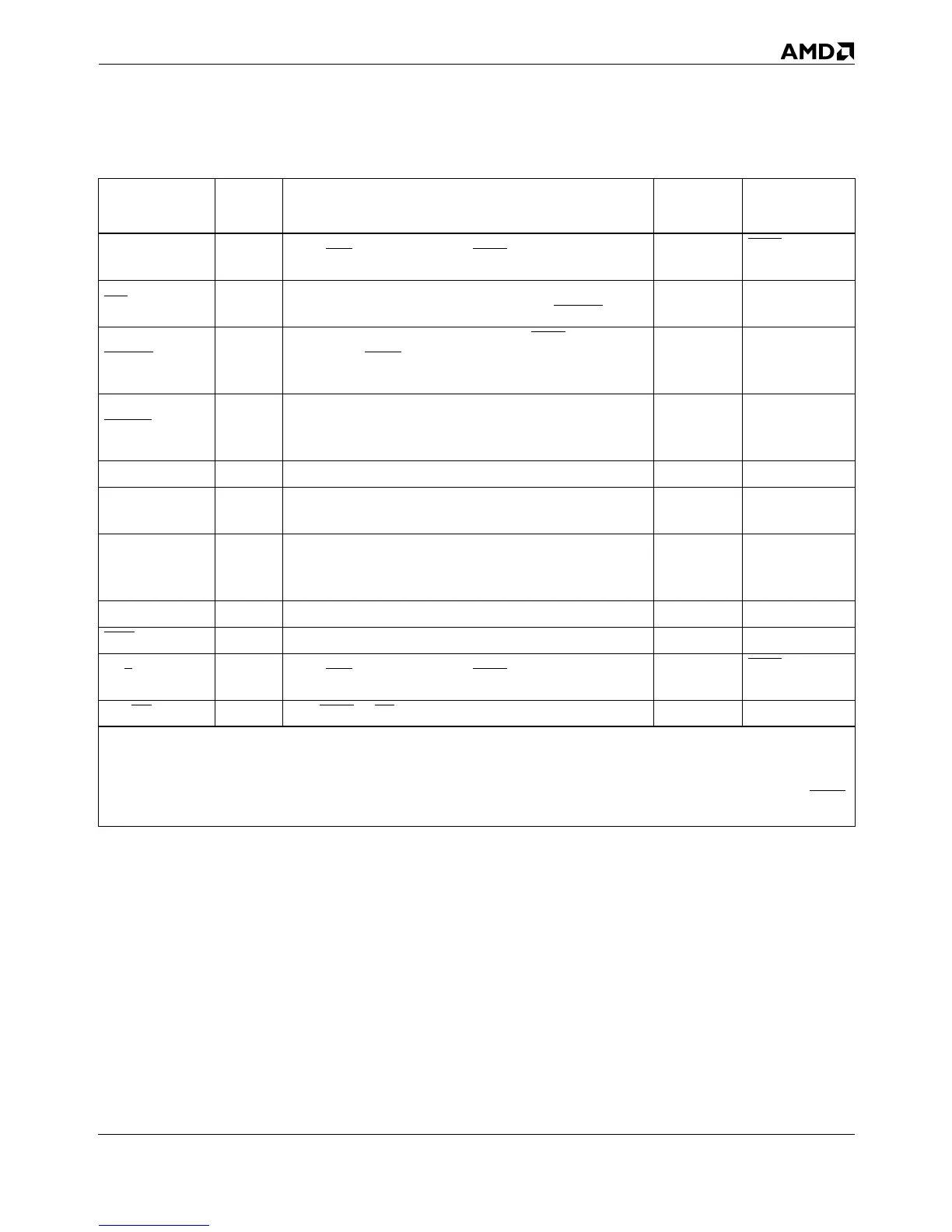
Table 5-2 shows the processor states, signal states, and bus
cycles during which the processor can drive or sample each sig-
nal. The table indicates when signals can be driven or sampled
so that their state has some practical (meaningful) effect on
the state of the processor or on the bus cycle being driven or
sampled. In Table 5-2, shading indicates signals that are mean-
ingfully driven or sampled. Signals that are not shaded are not
driven or sampled or are not meaningful. For details on how
each signal behaves, see Section 5.2 starting on page 5-17.
SCYC O From ADS until last expected BRDY of the bus cycle.
BOFF
+1 or
HLDA
SMI
1
I
Every clock. Falling-edge-triggered. Recognized at next
instruction boundary. Acknowledged with SMIACT
.
pullup
SMIACT
O
From one clock after the last expected BRDY
of the bus
cycle, while EWBE
is asserted, until the return from SMM
interrupt handler.
STPCLK
1
I
Every clock. Level-sensitive. Recognized at next instruc-
tion boundary. Acknowledged with Stop Grant special
bus cycle.
pullup
TCK I Always. pullup
TDI I
Every rising TCK edge during the shift_IR and shift_DR
states.
pullup
TDO O
Every falling TCK edge during the shift_IR and shift_DR
states.
While not in
shift_IR or
shift_DR state.
TMS I Every rising TCK edge. pullup
TRST
I Always sampled asynchronously. pullup
W/R
OFrom ADS until last expected BRDY of the bus cycle.
BOFF
+1 or
HLDA
WB/WT
I First BRDY or NA of bus cycle, whichever comes first.
Table 5-1. Summary of Signal Characteristics (continued)
Signal Type
Sampled (Input) or
Asserted (Output)
2
Internal
Resistor
Floated
3
Notes:
1. Can be driven asynchronously or synchronously.
2. The term clock means bus clock (CLK). “+n” means n CLKs later.
3. “+n” means n CLKs after the named signal is sampled active. All outputs and bidirectionals are floated during the float test (FLUSH
at RESET).