Signal Descriptions 5-85
18524C/0—Nov1996 AMD-K5 Processor Technical Reference Manual
2. Acknowledge—Drives an Interrupt acknowledge operation
(a cycle pair) on the bus. System logic must return a BRDY
in response to both cycles. Table 5-13 shows the signal val-
ues driven during the first and second bus cycles. Both bus
cycles are reads, but any data returned on the first cycle is
ignored. On the second cycle, the processor samples only
the enabled data byte (D7–D0) to obtain the interrupt vec-
tor. (The interrupt vector is an offset into an interrupt table
containing gate or segment descriptors.) The bus cycles are
driven as a locked pair, with a minimum of one idle clock
between the cycles and with LOCK asserted throughout.
System logic may respond as quickly as it is able; BRDY
operates in the normal manner to terminate each of the two
cycles. The first cycle is provided only for compatibility
with the original protocol; it carries no useful information.
3. Disable Interrupts—The processor clears the IF bit in the
EFLAGS register if (a) the processor is in Real mode, or (b)
the processor is in Protected mode and the interrupt vector
points to an interrupt gate or to a task gate that references
a TSS that has its IF bit cleared. (For details on how the IF
bit is managed in Virtual-8086 mode, see page 3-12.)
4. Service Interrupt—Using the interrupt vector as an entry
point, the processor saves its state and accesses a data
structure set up by the operating system. In Real mode, the
processor accesses the interrupt vector table (IVT); in Pro-
tected mode, it accesses the interrupt descriptor table
(IDT). The vector identifies one of 256 gates (descriptors) in
the table. The IDT, for example, can contain interrupt, trap,
or task gates, all of which point indirectly to the entry point
of an interrupt service routine.
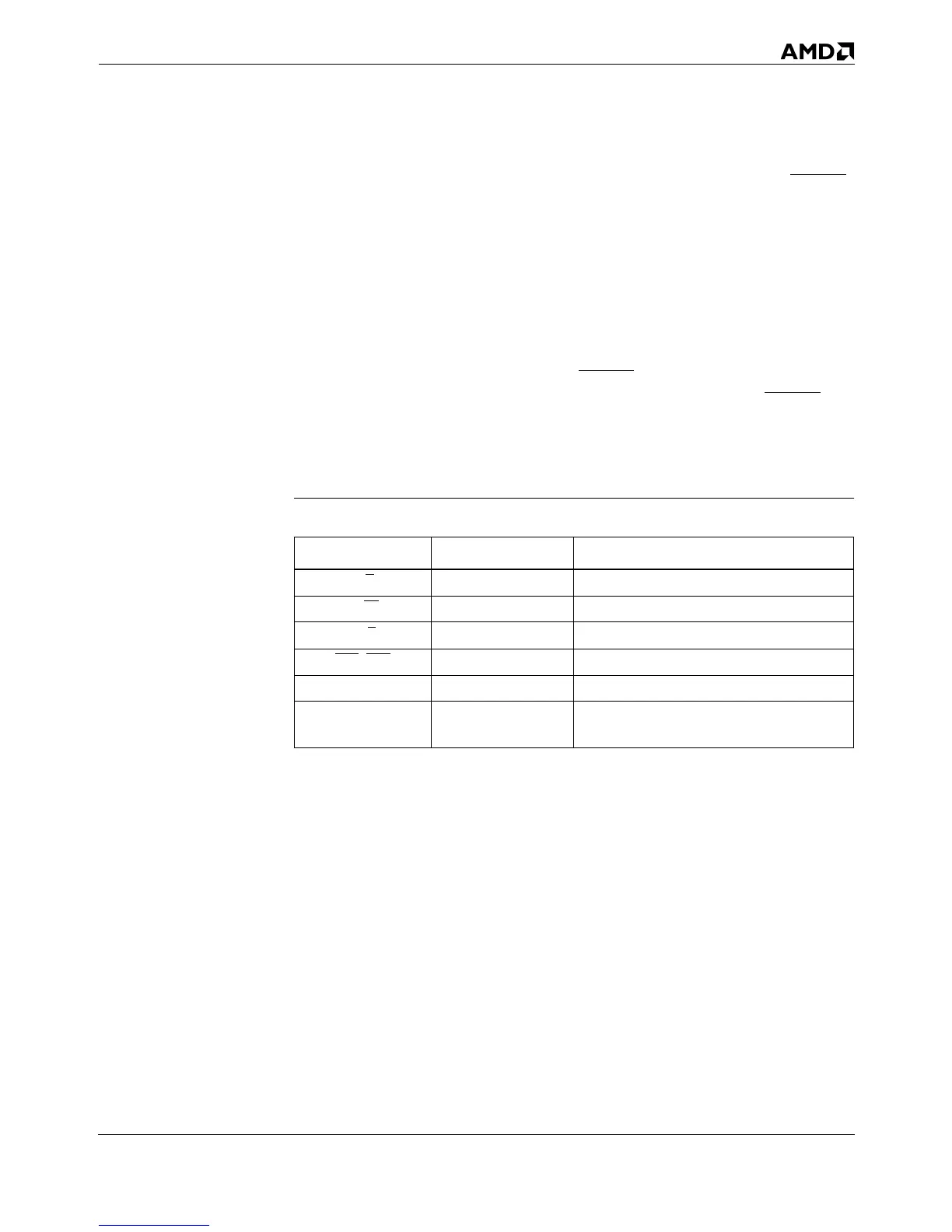
Table 5-13. Interrupt Acknowledge Operation Definition
Processor Outputs First Bus Cycle Second Bus Cycle
D/C
00
M/IO
00
W/R
00
BE7
–BE0 EFh FEh (low byte enabled)
A31–A3 0 0
D63–D0 (ignored)
Interrupt vector expected from interrupt
controller on D7–D0