Signal Descriptions 5-35
18524C/0—Nov1996 AMD-K5 Processor Technical Reference Manual
ships. This function of BE7–BE0 bears no relationship to the
D63–D0 data bus. This is particularly apparent in the case of
the Branch-Trace Message special bus cycle, during which the
value of BE7–BE0 is DFh (1101_1111b) but, in contradiction to
the byte-enable bits, the four bytes on D31–D0 carry valid data
during both cycles of the operation: during the first cycle, D31–
D0 carries the EIP value of the source (branch) instruction;
during the second cycle, D31–D0 carries the EIP value of the
branch-target instruction.
Certain models of the Pentium processor implement BE7–BE5
as outputs and BE4–BE0 as bidirectional signals. On the
AMD-K5 processor, however, all eight BE7–BE0 signals are out-
puts only.
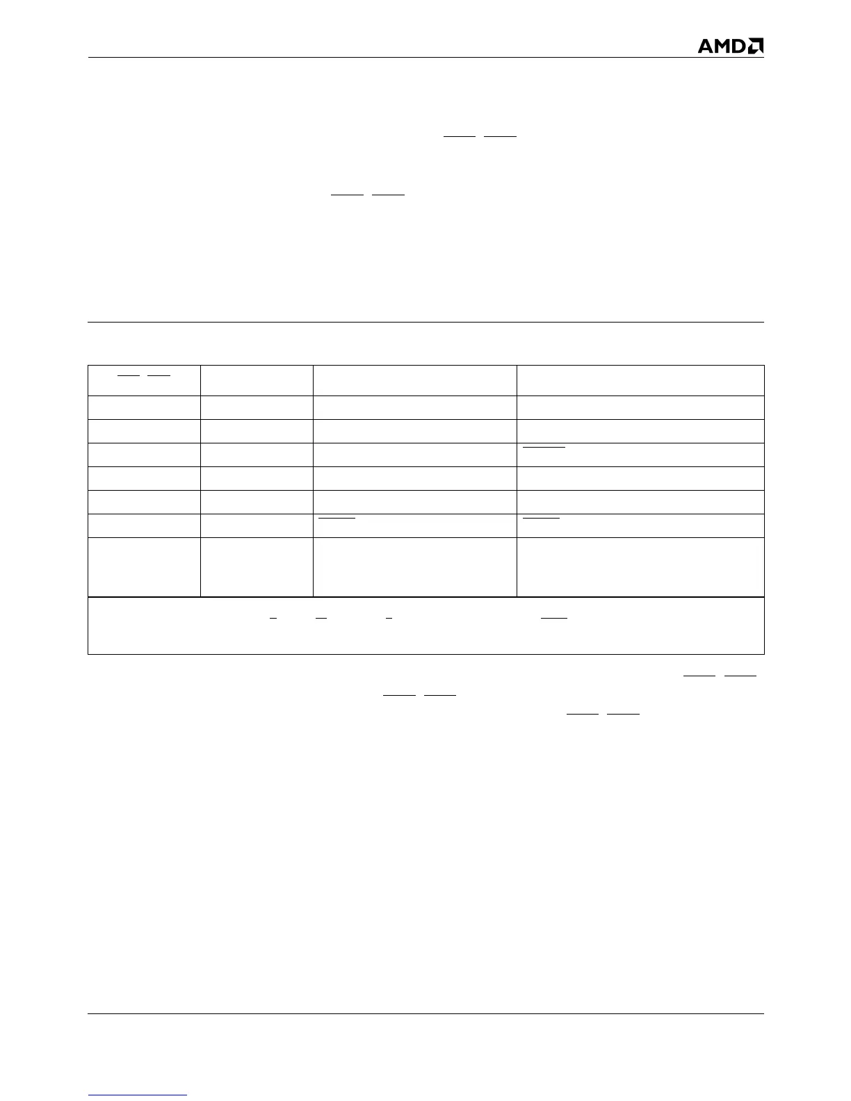
Table 5-6. Encodings For Special Bus Cycles
BE7–BE0 A31–A3
Special Bus Cycle
1
Cause
FEh ...00h Shutdown Triple fault
FDh ...00h Cache Invalidation INVD instruction
FBh ...10h Stop Grant STPCLK
FBh ...00h Halt HLT instruction
F7h ...00h Cache Writeback and Invalidation WBINVD instruction
EFh ...00h FLUSH
Acknowledge FLUSH
DFh ...00h
Branch-Trace Message
2
Bit 5 = 1 and bits 3–1 = 001 in the Hard-
ware Configuration Register (HWCR). See
Section 7.1 on page 7-3 for details.
Notes:
1. For all special bus cycles, D/C = 0, M/IO = 0 and W/R = 1. System logic must return BRDY in response to this cycle.
2. The message in a branch-trace message special bus cycle is different in the AMD-K5 and Pentium processors.