System Management Mode (SMM) 6-25
18524C/0—Nov1996 AMD-K5 Processor Technical Reference Manual
6.3.2 SMM State-Save Area
When the processor acknowledges an SMI interrupt by assert-
ing SMIACT, it saves its state in the 512-byte SMM state-save
area shown in Table 6-2. The save begins at the top of the SMM
memory area (SMM Base Address + FFFFh) and fills down to
SMM base address + FE00h.
Table 6-2 shows the offsets in the SMM state-save area relative
to the SMM base address. The SMM service routine can alter
any of the read/write values in the state-save area. The con-
tents of any reserved locations in the state-save area are not
necessarily the same between the AMD-K5 processor and the
Pentium or 486 processors.
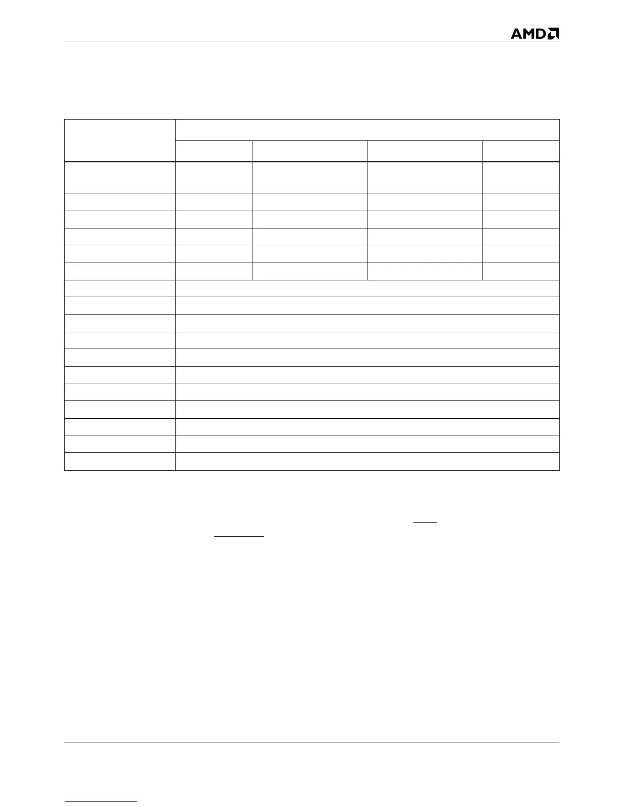
Table 6-1. Initial State of Registers in SMM
Register
Initial Contents
Selector Base Attributes Limit
CS 3000h
0003_0000h
(see Section 6.3.4)
16-bit, expand-up 4 Gbytes
DS 0000h 0000_0000h 16-bit, expand-up 4 Gbytes
ES 0000h 0000_0000h 16-bit, expand-up 4 Gbytes
FS 0000h 0000_0000h 16-bit, expand-up 4 Gbytes
GS 0000h 0000_0000h 16-bit, expand-up 4 Gbytes
SS 0000h 0000_0000h 16-bit, expand-up 4 Gbytes
General-Purpose Unmodified
EFLAGS 0000_0002h
EIP 0000_8000h
CR0 Bits 0, 2, 3, 31 cleared (PE, EM, TS, PG). Others are unmodified.
CR4 0000_0000h
GDTR Unmodified
LDTR Unmodified
IDTR Unmodified
TR Unmodified
DR7 Unmodified
DR6 Undefined