5-38 Bus Interface
AMD-K5 Processor Technical Reference Manual 18524C/0—Nov1996
BOFF provides the fastest response of the three bus-hold
inputs. Because of its ability to help resolve deadlock prob-
lems, it is required in almost all systems with multiple-caching
masters. In such designs, system logic typically drives separate
BOFF signals to each bus master in the system. See Section
6.2.5 on page 6-14 for system configurations using BOFF.
Unlike AHOLD and HOLD, BOFF does not permit an in-
progress bus cycle to complete. It forces the processor off the
bus in the next clock, aborting any in-progress bus cycle that
the processor has begun. A writeback can occur while AHOLD
is asserted, but a pending writeback during the assertion of
BOFF or HOLD waits until after BOFF or HOLD is negated.
The processor floats the bus one clock after the assertion of
BOFF. All output and bidirectional signals used for memory or
I/O accesses are floated. Table 5-8 shows the signals floated.
The same set of signals is floated with HLDA.
The processor supports only one in-progress bus cycle, no
pending bus cycles are buffered. If the processor is driving a
bus cycle when BOFF is asserted the processor retains the data
that had been transferred up to the clock in which BOFF was
asserted but ignores the data transferred with or after BOFF
was asserted. BOFF has no effect on writes to the processor
store buffer, except to delay them. (The store buffer is situated
between the execution units and the data cache. It is used for
speculative stores prior to being written to the data cache.)
The bus master asserting or causing the assertion of BOFF
must wait two clocks after asserting BOFF before driving its
first bus cycle because the processor does not float its outputs
until one clock after the assertion of BOFF. System logic or
another bus master may continue asserting BOFF for as long as
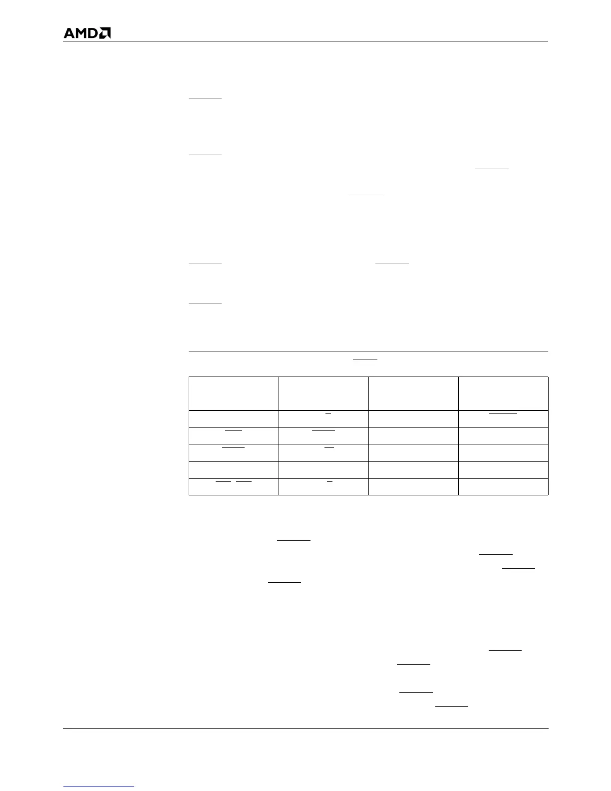
Table 5-8. Outputs Floated When BOFF is Asserted
Address and
Address Parity
Cycle Definition
and Control
Data and
Data Parity
Cache
Control
A31–A3 D/C
D63–D0 CACHE
ADS LOCK DP7–DP0 PCD
ADSC
M/IO N/A PWT
AP SCYC N/A N/A
BE7
–BE0 W/R N/A N/A