Bus Cycle Timing 5-187
18524C/0—Nov1996 AMD-K5 Processor Technical Reference Manual
Branch-Trace
Message Cycles
Figure 5-25 shows the two branch-trace message special bus
cycles that the processor generates for each taken branch
when branch tracing is enabled as described in Section 7.6 on
page 7-17. System logic can accumulate the address and data
bus values for debugging or profiling.
The processor drives these special bus cycles immediately
after each taken-branch instruction is executed. Both special
bus cycles have a BE7–BE0 = DFh, and system logic must
respond by asserting BRDY to each of the cycles. The first
cycle identifies the branch source, and the second identifies
the branch target, as shown in Table 5-24.
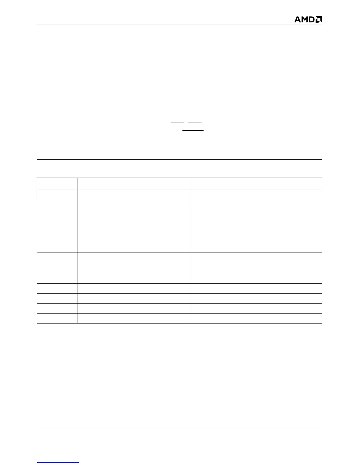
Table 5-24. Branch-Trace Message Special Bus Cycle Fields
Signals First Special Bus Cycle Second Special Bus Cycle
A31 0 = first special bus cycle (source) 1 = second special bus cycle (target)
A30–A29 not valid
Operating Mode of Target:
11 = Virtual-8086 Mode
10 = Protected Mode
01 = Not valid
00 = Real Mode
A28 not valid
Default Operand Size of Target Segment:
1 = 32-Bit
0 = 16-Bit
A27–A20 0 0
A19–A4 Code segment (CS) selector of branch source Code segment (CS) selector of branch target
A3 0 0
D31–A0 EIP of branch source. EIP of branch target.