5-110 Bus Interface
AMD-K5 Processor Technical Reference Manual 18524C/0—Nov1996
Starting at the falling edge of a recognized RESET, the proces-
sor performs the following actions, in the order shown:
1. Flush Pipeline—The processor invalidates the:
• Instruction pipeline
2. Reinitialize—The processor reinitializes the following
resources to reset values:
• General-purpose registers
• System registers
• Floating-point registers
• Model-specific registers (MSRs)
• Data-cache tag directory (linear and physical) and data
array. No writebacks are performed.
• Instruction-cache tag directory (linear and physical) and
instruction array
• Translation look-aside buffer (TLB)
• Branch-prediction bits
• Clears the interrupt flag (IF) in EFLAGS to 0
3. Jump To BIOS—The processor jumps to physical address
FFFF_FFF0h, the same entry point used after INIT, where
it expects to find the BIOS entry point.
The contents of AMD-K5 processor registers at the conclusion
of RESET or INIT is identical to that of the Pentium processor,
except that the CPU ID in EDX is 0000_050xh. The upper byte
of DX (DH) contains 05h and the lower byte of DX (DL) con-
tains 0xh, the processor’s type and stepping identifier.
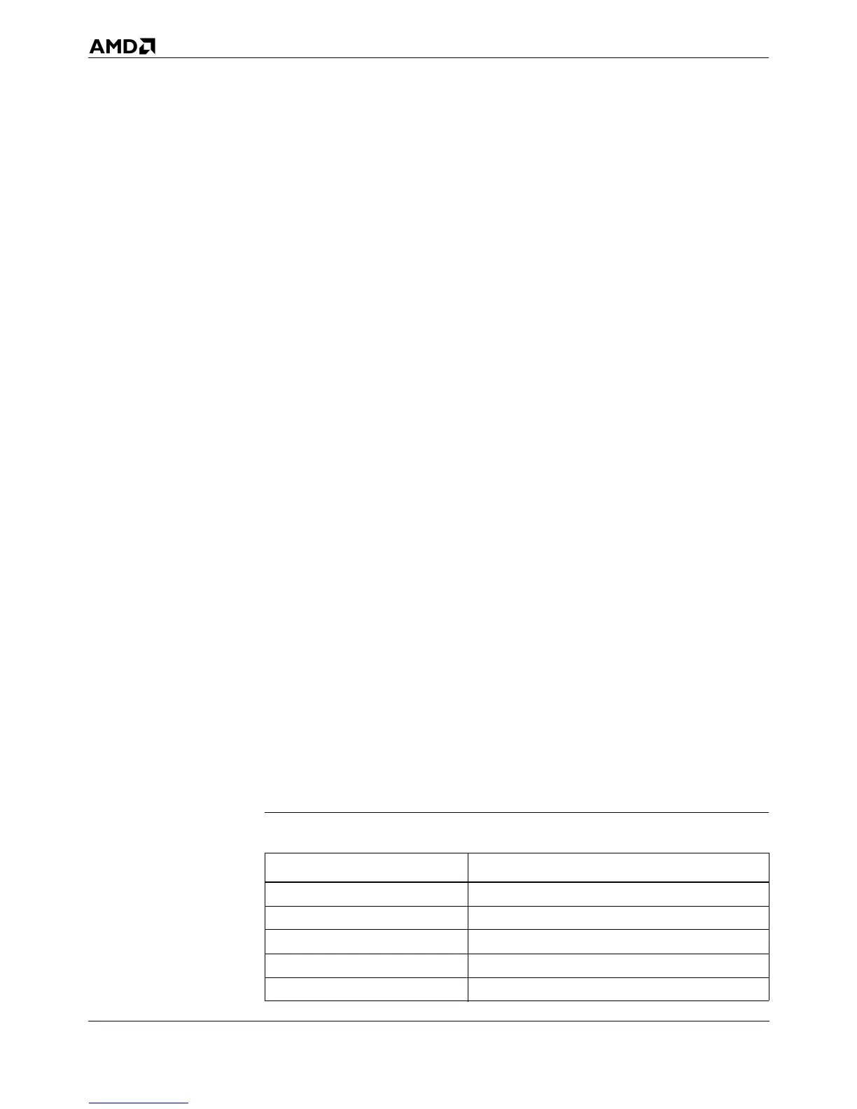
Table 5-15 shows the contents of registers after RESET or
INIT. Table 5-16 shows the state of the processor’s outputs
after RESET.
Table 5-15. Register State After RESET or INIT
Register
Contents (hex)
EIP FFFF_FFF0
EFLAGS 0000_0002
EAX 0000_0000
EBX 0000_0000
ECX 0000_0000