223
Images in the Signal Selection block
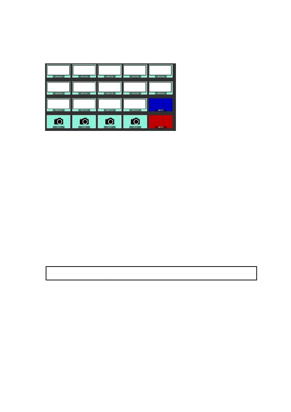
Images in the Signal Selection block show SCREEN 03-16 in the MV 3 image as shown below.
Therefore, images can be changed in [SETUP > MULTI VIEWER > MV3] menu PAGE 2 after
setting DIV to 16 in PAGE 1.
To perform simultaneous multiple bus transitions
Clicking TIE, then multiple bus buttons allows you to perform TIE transitions.
KEY layer display
Key layer display allows you to verify the layer order of KEY1-4 or FLEXaKEY1-4. The
top-most key in the key layer display represents the upper-most layer in the screen. To change
layer order, click a line and press arrow keys.
WIPE and PATTERN icons
Clicking WIPE or each pattern icon opens the relevant PATTERN menu.
Transition Rate display
Clicking the transition rate value opens the transition rate setting menu.
Enter the value and press the Enter key or click anywhere outside the Transition Rate field to
apply the change.
Restrictions on AUX signal change
To change an AUX bus signal (AUX1-12), the AUX bus should be assigned to LINE1 or LINE2.
Otherwise, signal selection and transitions using AUTO or CUT are disabled in this page.