05/2014
7-3
DC SC2020
Wiring Data
7.1 Plug/Jack Location List
Version 1.1
7.1.1 Plug/Jack Location List
How to Use the Plug/Jack Location List
• To find which position to install specific connectors to, refer to the table ’Plug/Jack Location List ’ for
Figure No. and Item No., and then to the figure in ’Plug/Jack Positions.’
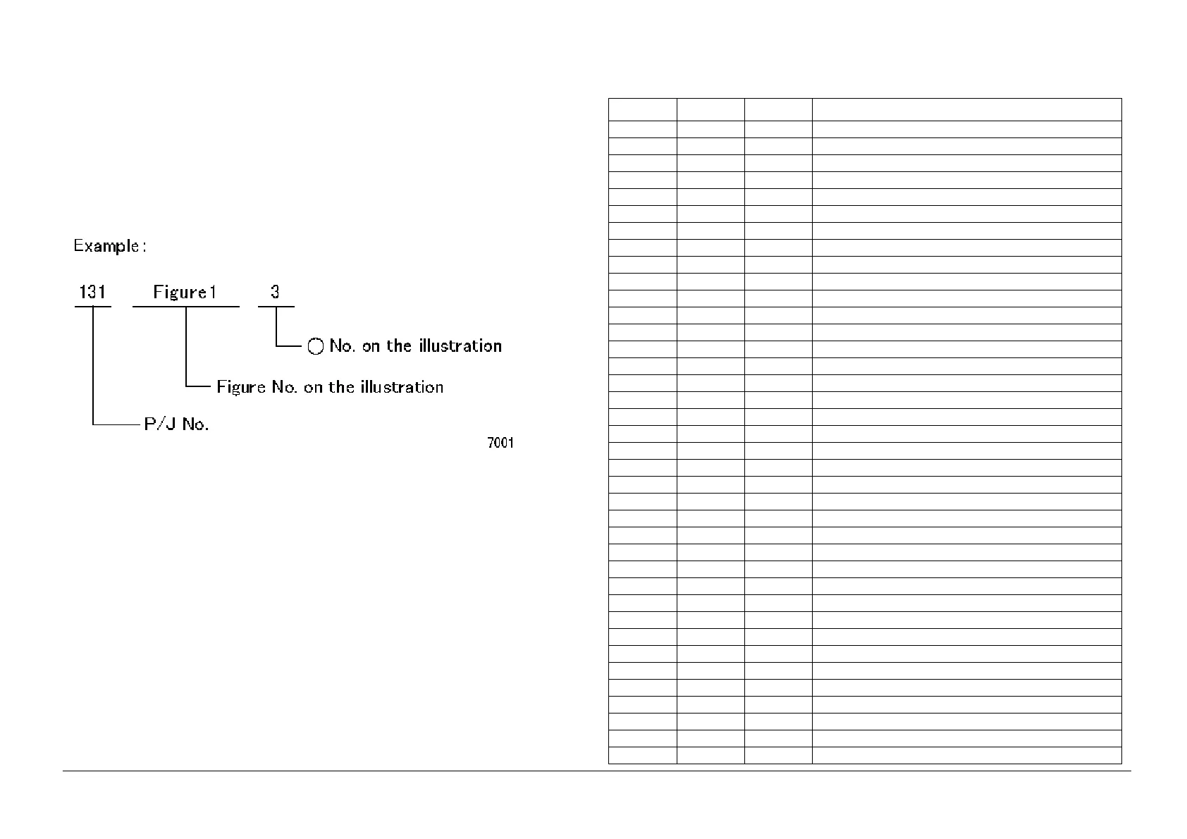
• P/J No. on ’Plug/Jack Location List’ is expressed in the four ways below:
• J250 represents Jack 250.
• P250 represents Plug 250.
• CN1 represents Connector 1.
• FS1 represents Faston Terminal 1.
Figure 1 7001
Plug/Jack Location List
Table 1 Plug/Jack Location List
P/J Fig Item Remarkes (where to Connect)
P/J1 921Drive PWB
P/J1 3 13 UI PWB C
P1 10 6 LVPS (Connect to J510)
J1 11 17 AC Inlet
J1 8 15 ESS PWB
P2 3 10 UI PWB C
P2 10 5 LVPS (Connect to J511)
J2 11 15 AC Inlet
P3 3 9 UI PWB L
P/J3 3 11 UI PWB C
P3/J3C 8 5 ESS PWB
J3 11 13 Main Power Switch
J4 11 12 Main Power Switch
P5 3 8 UI PWB C (Connect to J840)
P5/J5C 8 6 ESS PWB
J5 11 19 Main Power Switch
P/J6 8 4 ESS PWB
J6 11 18 Main Power Switch
J7 11 16 AC Inlet
P/J9 8 13 ESS PWB
P/J10 8 11 ESS PWB
P/J11 8 10 ESS PWB
P/J12 8 9 ESS PWB
P/J13 8 16 ESS PWB
P14 8 3 ESS PWB (Connect to J421(DADF))
P/J15 8 2 ESS PWB
P/J19 8 1 ESS PWB
P40 8 17 ESS PWB (Debug)
P/J100 4 8 Waste Toner Bottle Full Sensor
P/J101 4 4 Toner CRUM Connector Assembly (Y)
P/J101 12 1 Tary 2 Paper Size Sensor
P/J102 4 3 Toner CRUM Connector Assembly (M)
P/J103 4 2 Toner CRUM Connector Assembly (C)
P/J104 4 1 Toner CRUM Connector Assembly (K)
P/J104 12 5 STM Left Cover Switch
P/J105 5 1 Xero CRUM Connector Assembly (Y)
P/J106 5 1 Xero CRUM Connector Assembly (M)
P/J106 12 8 Tray 2 No Paper Sensor
 Loading...