05/2014
2-77
DC SC2020
Troubleshooting
CHAIN 62
Version 1.1
(The first 2 digits "10" in "1000" are the upper digits, which indicates the LED Lamp Wire Har-
ness. The lower 2 digits "00" indicates that nothing is applicable (no failures).)
NOTE:
Perform IIT diagnostic and then call NVM [715-030] again (press the Change Settings button) to
check the value (diagnostic result).
4. After replacing the appropriate parts, again change the value for NVM [715-030] to ’1’ and then per-
form "NVM Write".
5. Check that the current value column becomes ’0’.
6. If the problem persists after performing the above procedure, check the following:
• Out of Lamp (CIS Sensor Assy) (IIT Output[062-002]). (PL 1.3)
• Disconnection, shortage or contact failure of wire between CIS Sensor Assy J700 and ESS
PWB J15 (Especially check to see that the Flat Cable is not inserted in an angle).
7. If no problem is found, replace the ESS PWB. (PL 18.2)
062-380 AGC Fail
BSD-ON:CH6.3
Insufficient lamp brightness was detected when performing AGC.
Initial Actions
Check whether there is something blocking the light and check the Lamp, Lens, Mirror, and White Color
Correction Plate for deterioration or contamination.
Procedure
1. Turn the Power ON and enter CE Mode. Change the value for NVM [715-030] to ’1’ and then per-
form [NVM Write].
2. A 3 or 4-digit number is displayed in the current value column.
3. Check the upper 1 or 2 digits, or the lower 2 digits using the following table and replace the appro-
priate parts.
Sample Display
• 110 (3-digit display):
LED Lamp failure and LED Lamp Wire Harness is damaged or has poor contact.
(The first digit "1" in "110" is the upper digit, which indicates the LED Lamp ("0" in "01" is not
displayed). The lower 2 digits "10" indicates the LED Lamp Wire Harness.)
• 1000 (4-digit display):
The LED Lamp Wire Harness is damaged or has poor contact.
(The first 2 digits "10" in "1000" are the upper digits, which indicates the LED Lamp Wire Har-
ness. The lower 2 digits "00" indicates that nothing is applicable (no failures).)
NOTE:
Perform IIT diagnostic and then call NVM [715-030] again (press the Change Settings button) to
check the value (diagnostic result).
4. After replacing the appropriate parts, again change the value for NVM [715-030] to ’1’ and then per-
form "NVM Write".
5. Check that the current value column becomes ’0’.
6. If the problem persists after performing the above procedure, check the following:
• Out of Lamp (CIS Sensor Assy) (IIT Output[062-002]). (PL 1.3)
• Disconnection, shortage or contact failure of wire between CIS Sensor Assy J700 and ESS
PWB J15 (Especially check to see that the Flat Cable is not inserted in an angle).
7. If no problem is found, replace the ESS PWB. (PL 18.2)
062-386 AOC Fail
BSD-ON:CH6.3
A CCD output error was detected when performing AOC.
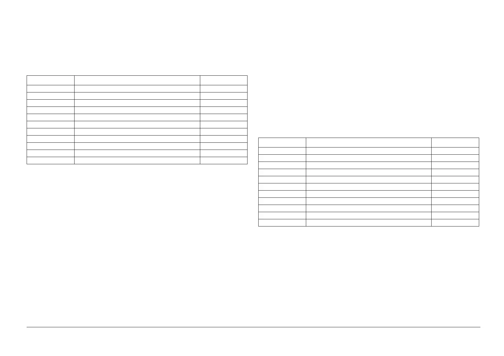
Table 1
Current value Component Name PL No.
00 Not applicable (No errors) -
01 Lamp (CIS Sensor Assy) PL 1.3
02 CIS Sensor Assy PL 1.3
03 Flexible Flat Cable (CIS Cable) PL 1.3
04 This value is not displayed -
05 This value is not displayed -
06 This value is not displayed -
07 This value is not displayed -
08 This value is not displayed -
09 This value is not displayed -
10 This value is not displayed -
 Loading...