2. Continue to pass the at cable and wire through the opening in the chassis (callout 1), and then insert
the hinges (callout 2) into the slots.
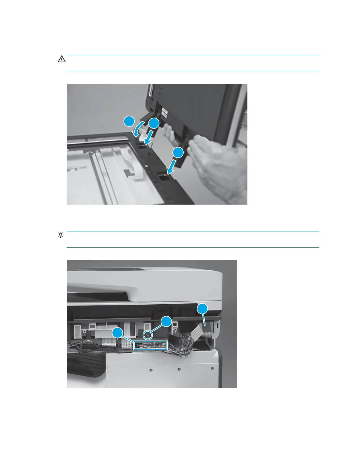
CAUTION: Do not damage the at cable or wire harnesses when the cable guide (callout 1) is installed
in its slot.
Figure 1-612 Install the document feeder
3. Connect one at cable (callout 1), install one ground screw (callout 2), and then connect ve connectors
(callout 3).
TIP: Close the document feeder as shown to make it easier to connect the connectors and install the
ground screw.
Figure 1-613 Install the ground screw and connect the connectors
Step 5: Install the SCB cover
1. Align the tabs on the back side of the SCB cover with the slots in the printer.
378 Chapter 1 Removal and replacement ENWW
 Loading...