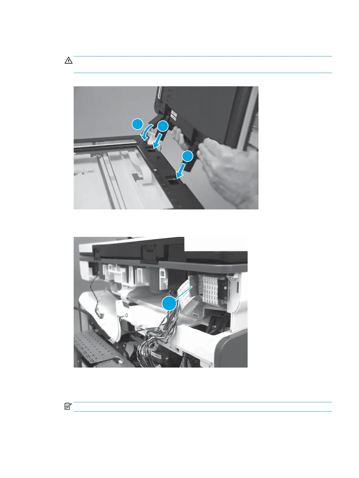
2. Continue to pass the at cable and wire through the opening in the chassis (callout 1), and then insert
the hinges (callout 2) into the slots.
CAUTION: Do not damage the at cable or wire harnesses when the cable guide (callout 1) is installed
in its slot.
Figure 1-710 Install the document feeder
3. Connect one at cable.
Figure 1-711 Connect the at cable
Step 13: Install the SCB (M586)
1. Position the SCB (callout 1) in the slot (callout 2) in the printer.
NOTE: Make sure that all of the cables are outside of the slot before installing the SCB.
ENWW Removal and replacement procedures 433
 Loading...