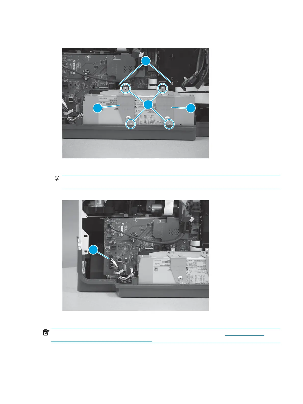
3. Install two brackets (callout 1), install four screws (callout 2), and then install two screws (callout 3).
Figure 1-945 Install brackets and screws
4. Connect one connector (callout 1).
TIP: This connector might take more than normal force to connect. Make sure it is full seated into the
connector body.
Figure 1-946 Connect one connector
Step 18: Install the formatter and formatter cage (PM)
NOTE: This step is for the 556 printer. For the 586 printer, skip this step and go to Step 10: Install the
formatter and formatter cage (586) on page 464.
1. Install the formatter and formatter cage assembly.
ENWW Removal and replacement procedures 565
 Loading...